diy solar

diy solar

It's all Wills Fault!!

Mac6792

Solar Enthusiast
Joined
Oct 30, 2019
Messages
148
So a while ago I'm just minding my business looking at cat videos on youtube and I stumble across a Will Prowse video. 4 months later I have this in my basement!!! - Thanks for your inspiration Will. I watched your videos and said - Hey I can do that!. After a lot of watching and reading I came up with a design to suit my use case. Moving from Design to reality resulted in a LOT of trips to Lowes and Home Depot. I think my wife suspects I'm having an affair with the Checkout girl at Lowes.
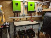
IMG_20200206_083532.jpg

One design element I struggled with was my desire to feed the Transfer switch with both Solar and a gas generator (not at the same time) and how to wire that. What I'm doing is using double pole switched where I'm disconnecting the Hots for each respective Power source. the Neutrals are all still wired together. To be more clear I have one 10 Ga 3 wire run (2 hots Neutral and Ground) as seen on the left side of the schematic. All power sources are sharing the same wires however the hots are switched on or off prior to connecting to the Run going to the Transfer switch. The neutrals however are all connected throughout (not switched) so any feedback would be appreciated on the implications of that. Also feedback on any other safety issue or gaps I have would be much appreciated
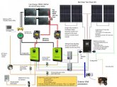
Solar Design(2).jpg
 

Attachments

  • Solar Design(2).pdf
    872.1 KB · Views: 12
Last edited:
Bitchin! Or sweetness! That is something for 4 months acquaintance.

Equipment ground bonding for the gen set accomplished through the combiner, nice enclosures and conduit, mini gutter, sps type outlets?, great design architecture and outfitting, layers of transfer switching amd source options..... drawings! Fun stuff.

Only thing aside from uncovered point to point on wall (i have also done this :( ....
And once a build has hit this level, the automotive circuit breakers, while practical may need some deep soul searching!

Let the inverter and panelwork handle neutral and the transfer switch -can be manual- will only have current from one source so inverter or inverter feed panel is line, likely.

Place the generator/ gen feed panel and grid/grid panel on the accessory transfer switch line connections and the load is your re gear/related, backed up load panels.

You will need a fused disconnect between the utility tap (next to the meter usually) and the next piece of equipment if the pv/transfer switch system.

In this line side tap, the tap blocks (insulated bus) are on the service conductors feeding the whole house transfer switch.20190507_132648.jpg
 
Bitchin! Or sweetness! That is something for 4 months acquaintance.

Equipment ground bonding for the gen set accomplished through the combiner, nice enclosures and conduit, mini gutter, sps type outlets?, great design architecture and outfitting, layers of transfer switching amd source options..... drawings! Fun stuff.

Only thing aside from uncovered point to point on wall (i have also done this :( ....
And once a build has hit this level, the automotive circuit breakers, while practical may need some deep soul searching!

Let the inverter and panelwork handle neutral and the transfer switch -can be manual- will only have current from one source so inverter or inverter feed panel is line, likely.

Place the generator/ gen feed panel and grid/grid panel on the accessory transfer switch line connections and the load is your re gear/related, backed up load panels.

You will need a fused disconnect between the utility tap (next to the meter usually) and the next piece of equipment if the pv/transfer switch system.

In this line side tap, the tap blocks (insulated bus) are on the service conductors feeding the whole house transfer switch.

Let the inverter and panelwork handle neutral and the transfer switch -can be manual- will only have current from one source so inverter or inverter feed panel is line, likely. Cool so just switching the hots is likely OK?

Place the generator/ gen feed panel and grid/grid panel on the accessory transfer switch line connections and the load is your re gear/related, backed up load panels. If I'm understanding you correctly - use the Gas gen feed a circuit in the transfer switch that is actually feeding my 2 AC inputs to the Inverters? Yup - already doing that! I'm planning to use the genny to charge the batteries if need be

You will need a fused disconnect between the utility tap (next to the meter usually) and the next piece of equipment if the pv/transfer switch system. - I don't show that in my drawing but I have a text placeholder for what I'm doing. I have a FireRaptor Rapid Shutdown system that has a shutoff button outside my house next to my electrical service. My AC feed TO the transfer switch first goes outside to a Fused Shutoff (that powers the rapid shutdown box) and then back in the house to the transfer switch. That way shutting off this switch kills the AC coming from the batteries via the inverter.

Note that this is entirely off grid - not grid tied
 
Ah, for off grid...

Generator is grid, if you need more power from backup generators to loads than inverters can handle, a load center/distribution panel with say the heavy shop loads on it and the inverter inputs.

Do the inverters have transfer switches incorporated? Maybe a misunderstanding. Are you just looking to feed through the inverter and power house loads directly from the gen set?

Usually this is accomplished inside the inverter.
I have a 10 port transfer switch (hanging of my house panel) that is covering my critical loads. It has double throw switches so I can have anything on or off grid at any time. The Off grid power comes from both the inverters or the Generator should that be necessary(but not at the same time). I can feed the entire transfer switch with the generator - One of the circuits on that transfer switch is feeding power to the outlets that the inverters are actually plugged into - So In that use case I could be feeding my loads with the gas generator AND charging my batteries (Both inverters would be turned off while doing this)
 
Switching hots is fine. There is no power down the neutral unless hot touches it on that circuit.
Note the common neutral bus, ground bond and service disconnect breaker in the image.
 
Back
Top