diy solar

diy solar

Neutral wiring question for 2 inverters

wsaharem

New Member
Joined
Jun 14, 2023
Messages
39
Location
Texas
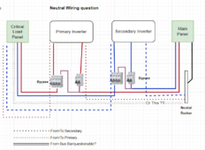
I have question related to neutral wiring using 2 inverters AND bypass switches for each of the inverters. My inverter wiring diagram is straight forward, L1/L2 + neutral in from grid panel, and L1/L2+neutral out to load panel(for each inverter). But when I add the bypass, would I be running 4 neutrals to the load panel with the 2 additional neutrals coming from the grid panel? (logically doesn't make sense to me) I've attached a picture of where my head is at.

Can any of the neutrals be shared with busbars? (IE, running all the inverter out neutrals to 1 busbar, then 1 wire to the load panel? (since everything will be joined together already in the neutral busbar in the load panel). I guess I'm asking if I can optimize the wiring of the neutral wires and a second question of the right electrical flow from the load panel. (a post from @Hedges regarding Auto-transformer L1/N/L2 current had my head swimming)
But he also said in a different post (with diff question) " I don't think it is necessary to switch neutral.
Neutral should follow path and be in same conduit as L1/L2 where current is flowing. I would even make a loop out of N if necessary to achieve that, but having multiple circuits enter and exit through same conduit could avoid that, and having all three circuits enter the switch through a single branch would mean N doesn't even need to go through it. (Similar to a light switch, just gets hot and switched, not neutral.)"

Thanks!
 

Attachments

  • NeutralWiring.png
    NeutralWiring.png
    66.8 KB · Views: 14
Several Questions
Are the inverters 120V or true 120/240V split phase?
You've appeared to show one phase going to primary and the other to the secondary, if red=L1 and blue=L2. Correct?
Is the bypass switch a true double pole double throw device?
If these are DIN-rail devices, is there a box to contain them?
If so, is it big enough inside to add a neutral bar at each and combine neutrals there?
 
Your schematic appears to show blue for one phase (e.g. L1) going to one inverter, red for other phase (eg. L2) going to other inverter. In that case, each presumably 120V.

But you mentioned L1/L2 for each inverter.

If each inverter is 120V, and stacked for 120/240V split-phase, then they can share a neutral. (At least so long as you don't also have AC coupled PV downstream; then inverters act like auto-transformer and neutral can carry higher current.

Often, neutral would daisy-chain through an inverter. OK to Tee off to them. Or to bypass ("Or this??" in your drawing) as well, on account of the bypass switch (That's the loop people might object to but I think I'm OK with.)

More clarity/detail about inverter model and 120 vs. 240 vs. 120/240V split-phase would help.
 
Several Questions
Are the inverters 120V or true 120/240V split phase?
You've appeared to show one phase going to primary and the other to the secondary, if red=L1 and blue=L2. Correct?
Is the bypass switch a true double pole double throw device?
If these are DIN-rail devices, is there a box to contain them?
If so, is it big enough inside to add a neutral bar at each and combine neutrals there?
True split phase dual pole inverters. The two colors represent the different inverters. Bypass is true dual pole L1/L2 for each input. There is a box with a din rail for the breaker & the bypass and it has both ground and neutral busbars .
 
Your schematic appears to show blue for one phase (e.g. L1) going to one inverter, red for other phase (eg. L2) going to other inverter. In that case, each presumably 120V.

But you mentioned L1/L2 for each inverter.

If each inverter is 120V, and stacked for 120/240V split-phase, then they can share a neutral. (At least so long as you don't also have AC coupled PV downstream; then inverters act like auto-transformer and neutral can carry higher current.

Often, neutral would daisy-chain through an inverter. OK to Tee off to them. Or to bypass ("Or this??" in your drawing) as well, on account of the bypass switch (That's the loop people might object to but I think I'm OK with.)

More clarity/detail about inverter model and 120 vs. 240 vs. 120/240V split-phase would help.

Sorry, seems I added confusion with the colors. They represent the inverters and not L1/L2. Rosie Inverters. True split phase 240V
 
Not enough lines to represent L1/L2/N going to each inverter. (eventually should include ground as well.)

Paralleling two L1 and paralleling two L2 should work fine for inverter output, given good inverter design.
Doing that for bypass from grid is more likely to have imbalance (something I experienced.)

I think Rosie supports 120V per inverter, for 3-phase. Maybe also for two inverters providing split phase. That may be better, or maybe not (less likely to support having extra inverter sleep with light loads.)

I haven't looked into Rosie's connection terminals.

You might consider a wiring box or conduit Tee, and using something like split bolt or Polaris to Tee off N and G to the inverters, rather than separate runs from Main panel to Critical Loads panel.

If there is any chance you would add GT PV downstream of Rosie, consider that it can act like an auto-transformer, taking in 240V and putting out 120V at 2x the current. In that case, having N wire from Rosie to critical loads panel sized 2x as large as L1 could be useful.
 
Answered my own question. The Neutrals are common inside the Rosies, so by following that logic, the bypass would also use the same common neutral.
 
Back
Top