diy solar

diy solar

Auto-transformer L1/N/L2 current

This is entertaining, Hedges, thank you for that.

I can't see it yet but my conceptual understanding of autotransformers is still limited. The diagrams are worth more than words thanks to both diagram drawers.

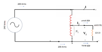
View attachment 207604
View attachment 207605
I don't see how the first one proves the second one. The first one makes perfect sense to me, and the second one looks wrong. I'm still open to the idea that I just don't understand the second one, and I'll keep trying to see if it clicks somehow.

Edit: Wait the second one only has a load on the 120v? So that makes sense then. What is the big revelation there, if you put 3 amps into a 240v-120v transformer you get 6 amps out, auto or isolation, isn't the question here about what a balanced load is doing?

The two drawings are identical except for amperage values and slight difference in current between the two windings, which I attribute to transformer no-load current; it is an inductor, so carries current based on V = L dI/dt

Phrased the other way, if you put a 6A (720W) load on 120V output of auto-transformer, it draws 3A (720W) from 240V supply. That much is obvious.

Kirchhoff's Law is also obvious.

Given both of those that (almost) everyone should agree on, it is clear that current has to swim upstream in one of the inductor windings. And center tap (neutral) current of auto-transformer is the sum of L1 and L2 current, which are both into the transformer (at the instant N current is out), and both out of the transformer (at the instant N current is in.)

Which gets us back to how transformer should be protected from overload.


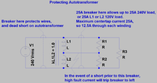
I say that if 25A is the max center-tap N current allowed from transformer, you have to protect L1 and L2 each at 12.5A.

If that breaker is placed between inverter and loads panel with auto-transformer hardwired, only 3kVA total is available whether on one 120V leg, the other 120V leg, or distributed. Safe, but limiting.

Someone might want to just connect auto-transformer through 2-pole 12.5A breaker, but of course you don't want to simply disconnect auto-transformer, leaving split-phase load panel fed from 240V. Lost neutral would cause over and under voltage to loads on each phase.

As safe way to protect from OCP could detect > 12.5A in L or > 25A in N, use that to disconnect inverter from loads panel. 12kVA from two inverters in that case, so 50A max operating current, 63A 2-pole breaker for combined inverter outputs, linked to 12.5A (?) breaker for auto-transformer.

That leaves the question of precisely what OCP value to use. If transformer can handle 12.5A on L1/L2 for 25A on N, a 12.5A breaker could nuisance trip unless continuous load does not exceed 80%, 20A on N. A 15A breaker would allow 25A continuous on N, but transformer might overheat if subject to 30A continuous.

To safely run closer to the limit, I'd prefer a magnetic-hydraulic breaker which doesn't require derating for continuous operation.

Or, use temperature sensor and remote-trip the 63A breaker. That's Victron's implementation. Thermostatic fan, too.
 
@Hedges Ok I think I see something what you mean now, maybe.

Is this all solved if we move the load to the other side of the autotransformer or something? I'm only at a hair brained thought here, but the other diagram looks like sort of like it has a load that's tapped onto a feeder.

Maybe you are already describing that there is a standard installation practice that is giving the problematic feeder current access.

Auto-transformer current.png
 
@Hedges Ok I think I see something what you mean now, maybe.

Is this all solved if we move the load to the other side of the autotransformer or something? I'm only at a hair brained thought here, but the other diagram looks like sort of like it has a load that's tapped onto a feeder.

Maybe you are already describing that there is a standard installation practice that is giving the problematic feeder current access.

View attachment 207706

I think the two diagrams are the same.
Standard grid-fed isolation transformer circuits aren't a problem, so long as OCP protects all windings from overload. I think that means OCP doesn't exceed what core can handle, and doesn't exceed what either secondary can handle. Which means with 240V load on output, windings are at 50% of current rating but with 120V load they are at 100%.

For auto-transformer I don't think where the 120V load goes fixes anything. Works the same between L1/N and L2/N, perfect symmetry.

240V loads can go to a dedicated panel fed directly by inverter.
But the issue is, auto-transformer can only handle a limited imbalance of 120V loads between L1 and L2. With a simple overload protection scheme, breaker protection allowing 3000W (25A) imbalance only allows 3000W combined 120V loads on L1 and L2.

A more clever scheme monitoring imbalance and disconnecting 12kW of inverters allows any loads which don't represent excessive imbalance.

The basic issue is small cheap autotransformer on a much higher wattage inverter system. And manufacturers who rate an autotransformer "5kW" when it can only supply a 2.5kW load.

I can repurpose a 25kVA utility transformer as auto-transformer and not need any OCP. That is what I did for this test. Sometimes they can be had cheap if within driving distance.
 
Are you streaming the raw time-domain sampled data from the sensor into LabView for analysis and doing FFTs there?

Labview drivers and Matlab instrument-control toolbox.

The data is probably streaming, don't think there is much memory in the hardware.
I don't know drivers. If I poll, I can't do transactions above about 300 per second. The vendors have lower level drivers to pull in real-time data.

So I make a call to Labview routines, get four channels of data in an array, process in Matlab from there.

I've used Labview much less. Once inherited a program in its flowchart style of code, with multiple pages of overlayed flowcharts. The code formatted a text stream to pass messages, and edited the text stream to insert fields (yuck!) That implemented a memory read function from a CMOS image sensor.

I'm more comfortable with lines of code and data structures, but can easily get over my head with large number of data points I can't really visualize but have to process. Takes code just look at it.

The concept is simple if I think of a compass near a bunch of magnets, and I'm flipping the magnets to cancel/minimize the field they present to the compass. Now do that with AC electromagnets, in a room with multiple phases, noise, and equipment switching on and off.

Just an analog circuit driving coils to zero field at a sensor seems so much simpler. But I'm trying to optimize reducing interference at some sources under my control.
 
Come here and play, @timselectric and @Cmiller, so we don't completely bamboozle @Joshua787 with our tech talk.

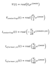
Since Tim doesn't like my referring to voltages or currents in a split-phase system as being 180 degrees apart or out of phase, here's a way to describe them without using the word "phase". Note the term "j pi" which describes current measured into current transformer center-tap (3rd trace on my scope) appearing as a sine wave inverted compared to into L1 and L2 (2nd and 4th trace)

1712701016672.png
 
@Hedges Ok I think I see something what you mean now, maybe.

Is this all solved if we move the load to the other side of the autotransformer or something? I'm only at a hair brained thought here, but the other diagram looks like sort of like it has a load that's tapped onto a feeder.

Maybe you are already describing that there is a standard installation practice that is giving the problematic feeder current access.

View attachment 207706

Now I follow you. By having the wire from 240V source hit autotransformer first, load second, we can put breaker feeding load from auto-transformer. That could be a 200A 2-pole breaker in L1/L2 if we want to limit neutral current to 200A, for instance. Or 25A for the 3kVA imbalance limit of Growatt auto-transformer from another thread.


1712706495886.png
 
My apologies @Hedges and @timselectric (as well as anyone else following our transformer discussion), my day did not go as planned and I did not get to this transformer test. I will try my best to get to it tomorrow!
 
Today I got around to doing this test. I am happy to say that I was wrong and @Hedges was right. (I suspected this after thinking things through.)

I got quite a few pictures and funny enough, this test fit in very well with some testing that I needed to do anyway for another project! I'll try to add a few pictures later tonight, and then either tonight or tomorrow I'll start a new thread with extensive details, as I was re-purposing a Schneider SW4048 transformer, and was also testing both 120v in to 120/240v out as well as 240v in to 120/240v out.
 
Back
Top