diy solar

diy solar

Auto-transformer L1/N/L2 current

Hedges

I See Electromagnetic Fields!
Joined
Mar 28, 2020
Messages
20,761
Transformers aren't well understood by most people who use them.
It is well known that centertap "Neutral" connection carries the difference between L1 and L2, but that is not at all true for autotransformers. It is only true for the case of an isolation transformer where all power is delivered to the primary (e.g. from the grid.) If an isolation transformer is backfed (e.g. by grid tie photovoltaic inverter), it is no longer true.

In an autotransformer, the centertap neutral current is the sum of L1 and L2. L1 equals L2. L1 and L2 are (approximately) zero unless there is a load that draws current from neutral. I say "approximately", because real transformers aren't ideal, and manufacturing makes a tradeoff between performance, and cost/size; see link below under "References".

After debating this issue to no end with other electrically experienced members on the forum, I finally wasted a morning putting my measurement where my mouth is.

Consider a 120V load (oil filled radiator), 240V source (grid L1/L2), and autotransformer (Two 240V primary windings of 240/480V to 120/240V transformer in series, secondary open circuit.) Note that the source is ground referenced, unlike a typical European 240V inverter with its "N" output disconnected from ground - for this reason I did NOT bond centertap N to G as you normally would.
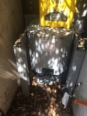
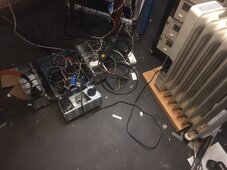
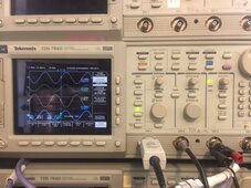
Transformer IMG_4786.JPG mess on floor IMG_4782.JPG scope IMG_4781.JPG

For this test, 15A breaker fed 240V L1/L2 to autotransformer, but N was not connected to grid.
Three CT (333mV/100A) were installed on L1/N/L2 of auto-transformer, all pointing toward auto-transformer
L1 from breaker also feeds hot pin of an outlet (not through CT). N coming back from auto-transformer goes through CT to neutral of outlet.
Electric heater is plugged into outlet, and scope voltage probe is also plugged in.

In screen shot, trace #1 shows L1 to N is 123.3 Vrms,
L1 current into auto-transformer is in phase, 3.72A ("V" means "A"),
N current into auto-transformer is out of phase 7.05A (so -7.05A)
L2 current into auto-transformer is in phase, 3.33A
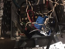
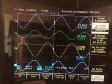
CT and plugs IMG_4784.JPG Scope traces IMG_4780.JPG

Note that 3.72A + 3.33A = 7.05A, so Kirchhoff's current law holds true!

Ordinarily, if you connected a load across 240V L1/L2, you would expect current to flow in L1, out L2. Then when polarity of AC reverses, in L2 and out L1.
The key thing to note is that does NOT occur here [in the case of auto-transformer as "load"]. Current flows in L1 AND in L2. It flows out N.
The load applied between N and L1 causes current to flow from L2, through transformer winding, out N, through the load, back to grid on L1.
That current flows through transformer winding ONLY because (approximately?) equal current also flows through the other winding in the opposite direction.

I understand all of this hurts your head. I had trouble wrapping my mind around it (and for real fun, study "hysteresis" and "saturation"; you can even use transformers in place of transistors to dim stage lighting or modulate AM radio broadcasts!

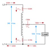
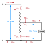
But the following diagram actually makes autotransformer operation clear. If you can give up preconceived notions.
Auto-transformer current.png


References:

 
Last edited:
In other news, 3.72A - 3.33A = 0.39A, pretty close to "Only 0.36A drawn" in my referenced test where I applied 120V to a 240V primary winding.

Not sure if there should have been a 2x or 0.5x multiple in there, but superimposing the no-load current with auto-transformer induced current seems correct.
 
@timselectric , you had some measurements that challenged my claims. Can you link those here?
If I could find them, I would.
I'll do some testing, when I get time.

Actually, there's too much information to correct in this thread. (Phasing and current flow)

And I really don't want to go through it, all over again.

I will do the testing and make the results available.
Just not in this thread.
 
Last edited:
My understanding on this subject is a bit different coming from a different background the neutrals job is to carry the unbalanced.load back to its source, in standard split phase system when you pull a 240v source from 2 120v legs you have a balanced circuit and there should be no load on your neutral(you will see the difference of each each leg) Now when your splitting a 240v leg like you do with the auto TX there is no way to balance that load since your only using 1 leg to supply 2 120v legs this is the same reason we are required to use a 2 pole breaker on multiwire branch crcuits.if you place 2 breakers on the same phase and share that neutral you are effectivly doubling your unbalanced load on that circuit. Hiw hiver if you have that same 3 wire branch on a proper 2pole breaker your 2 loads (if they have the same draw) will cancel out any current on the neutral.
 
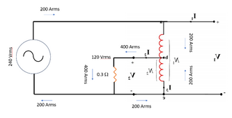
@Hedges Is the following diagram an accurate representation of your setup and measurements?

View attachment 207572

Yes, although I'm not 100% certain which winding in the drawing was 3.33A and which was 3.72A. I suspect they're reversed, given the bias of no-load current, which sums with current fed to load for upper coil, subtracts for lower coil.

You put arrows for CT(L1) and CT(L2) facing each other, which also represents direction CT is oriented. CT(N) could also have an arrow oriented into the transformer, to the left.

Of course RMS current readings are all positive. I just assigned negative to indicate the waveform was inverted on the screen, the instantaneous current is in opposite direction through that CT. The instantaneous current would go to peak in each direction, but also passes through a (signed) value same magnitude as RMS, convenient for our notation. (I'll use equation editor to correctly format it using Euler's identity just so as to not use the word "phase" that Tim objects to in this context.)

Line voltage is likely 250V, that's what I usually see.

It is to be expected (I think) that voltage across upper winding rises due to current forced through it times resistance, and voltage sags across lower winding due to it magnetically forcing current the "wrong" way. But my brain isn't working so clearly (not sure if due to Long Covid, Long Vax, or Long Electrocution). Or maybe I'm just easily confused*.


*At work I've been beating my head against digital signal processing of triaxial time domain magnetic field measurements, converted by FFT to frequency magnitude and phase, subtracting two readings as I reverse polarity applied to each electromagnetic component in a system. I want to quantify the contribution of eight sources, determine which of 128 possible phase (Take that, Tim!) relationships between them would minimize magnetic field at a sensitive area of the system.

I was initially thinking I'd get a linear vector (X^2 + Y^2 + Z^2^0.5. First, I had to associate phase relationship of randomly timed scope (NI DAQ) captures, so I fed line voltage into 4th channel of scope (DAQ), ran FFT on it as well, subtracted complex number representing phase of voltage from the magnetic readings. As I had observed, the the "X" component was not in phase with "Y" component; this magnetic field isn't linearly polarized, it is elliptically polarized. Three phases present in the room (120 degrees apart), each could drive resistive (0 degree), capacitive 90 degree leading, or inductive 90 degree lagging loads and phase current. Of course loads are complex RL or RC, so anything from -90 to +90 degrees for each.

Rectifier-capacitor circuits in linear power supplies and LED lamps are inherently non-linear. They only gulp current when line voltage exceeds capacitor voltage, and width of that current pulse varies with loading. So the actual magnetic field traces out more like the outline of a potato chip (I think, haven't tried to plot yet) [Edit: Yup, looks like a potato chip]. But working with just 60 Hz FFT component, I think it has to fit in a plane, be elliptically polarized. The fact a sine-wave peak gets represented in FFT as multiple frequency components isn't helping anyway. (only if captured time window is an exact multiple of 1/60 would it be represented as a single frequency.)
 
Last edited:
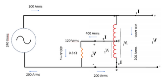
400A was not a measured case, just my notional design of how GT PV could overload utility's neutral conductor, without OCP protecting.

(7A was my test measurement. I used a 25kVA transformer as autotransformer.)

Consider 10 houses each with 40A load all on L1. Even if a transformer had OCP to prevent 400A on L1, 48kW of 240V PV in the neighborhood (200A on L1/L2), using utility transformer as auto-transformer, could cause this.

There's a 50kVA transformer underground in my front yard, supplies some quantity of homes.
 
You put arrows for CT(L1) and CT(L2) facing each other, which also represents direction CT is oriented. CT(N) could also have an arrow oriented into the transformer, to the left.
The arrows show current flow, the little red dots show the CT orientation.

*At work I've been beating my head against digital signal processing of triaxial time domain magnetic field measurements, converted by FFT to frequency magnitude and phase, subtracting two readings as I reverse polarity applied to each electromagnetic component in a system. I want to quantify the contribution of eight sources, determine which of 128 possible phase (Take that, Tim!) relationships between them would minimize magnetic field at a sensitive area of the system.

OK, now the "I See Electromagnetic Fields!" title makes perfect sense to me!
I hope you are doing those FFTs in real time and generating cool 3-D spectral images that move.
Just H-probes? or do you have E-probes too?
(I am not a Physicist)

The fact a sine-wave peak gets represented in FFT as multiple frequency components isn't helping anyway. (only if captured time window is an exact multiple of 1/60 would it be represented as a single frequency.)
However, I do know DSP.

You can do Goertzel algorithm if you just want a single FFT bin at 60.0 Hz, or tune it to the exact frequency.
No FFT scalloping loss or window functions needed.
But you'll need Matalb or Scipy and some data acquisition hardware.
 
This is entertaining, Hedges, thank you for that.

I can't see it yet but my conceptual understanding of autotransformers is still limited. The diagrams are worth more than words thanks to both diagram drawers.

1712460001514.png
1712460029132.png
I don't see how the first one proves the second one. The first one makes perfect sense to me, and the second one looks wrong. I'm still open to the idea that I just don't understand the second one, and I'll keep trying to see if it clicks somehow.

Edit: Wait the second one only has a load on the 120v? So that makes sense then. What is the big revelation there, if you put 3 amps into a 240v-120v transformer you get 6 amps out, auto or isolation, isn't the question here about what a balanced load is doing?
 
First One: I just tried to sketch out what he had written. Hopefully I didn't misinterpret what he said too much.
There are other autotransformer references out there, all of them should say the same thing with different notations and emphasis.
It's helpful, thank you for doing, and he seems to confirm you've drawn his test good enough. My remaining confusion is about his diagram.
 
I have seen Hedges propose a surprise neutral current in a grid tied inverter utility transformer edge case and been convinced of his proposed surprise.

I have also seen Hedges jump the gun and propose a surprise neutral current on a house circuit that we all eventually concluded wasn't there.

Hedges likes to find surprise neutral currents.

I do not know if I see the surprise here, I thought the proposal was that a 240v load on a 240v autotransformer could generate a surprise neutral current.
 
Hedges likes to find surprise neutral currents.
Not speaking for @Hedges, but I've certainly had a surprise house neutral current!

When I got my Victron Autotransformer I combined the house neutral and the AT neutral (naively).

This effectively put my grid transformer and autotransformer in parallel.
I had cheap ammeters on L1, L2, and N, and wow, I couldn't figure out what the hell was going on.
The autotransformer was balancing the other half of the house not on the critical load panels.

Once I saw what was going on, I ended up with a relay switching my critical load panel neutral from house to AT neutral when inverting.
 
This effectively put my grid transformer and autotransformer in parallel.
Parallel transformers sharing balancing is still a bit of a brain twister for me. I get the concepts of why it happens, but I'm lost on the variables. Like supposedly transformer inverters like the XW will always end up sharing some balancing current with the utility transformer whenever they are closed onto the grid? Are those suprise neutral currents inherently limited to safe levels somehow, idk.

But I just add it to the list of reasons I'm happy to have gone to double conversion.
 
inverters like the XW will always end up sharing some balancing current with the utility transformer
Well, how it works will depend on the impedance of the grid transformer secondary winding, the length of cable from the transformer to the meter, etc. In my case, I have 400A service split into 2x200A, and that other half had lots of unbalanced loads. Totally confused me.
 
I don't know Goertzel. Thanks, (I think!), maybe I can make use of that, but at first glance I'm in over my head.


What I did do was find highest peak in FFT of voltage (50 or 60 Hz), default to 60 Hz if not connected.
Then I computed harmonics, and scanned +/-0.5 Hz around them in the FFT data. Combined by RSS (not exactly "coherent" nor asynchronous peaks, not sure what proper method to combine would be.) I did this because when I tried subtracting one FFT from another, shoulders around peaks were prominent.

Sensor is a 3-axis Barrington fluxgate sensor, digitized by an NI 4-channel module.

I initially thought I should consider all harmonics, but 60 Hz fundament dominates. Best I figure I might do is cancel this local contribution at 60 Hz, reducing what "MFC" (Magnetic Field Compensation) system has to do. It is good at uniform fields, i.e. far fields. The things I'm dealing with are close, so produce a non-uniform field in the area of interest.
 
Back
Top