diy solar

diy solar

Question Regarding Max. Input Amps to Growatt Inverter

John_the_Axolotl

New Member
Joined
Jul 3, 2021
Messages
7
Hello everyone,
I hope all is well and the sun is shining for all. I feel like this question has been half answered, but not explicitly, so I was hoping that someone could do so :).
I have a Growatt SPF 3000TL. It has a 120v - 250v PV input range with a max of 18A from the PV. My question is regarding this max amperage rating. Let's say that I have a PV setup of 3s3p of panels with open circuit voltage of 37 (realistically producing 30v) and short circuit amperage of 8A. In theory, this is under the 250v max, but over the 18A max. Now, in reality, it would likely never produce this much amperage, but let's say that it does. Would the inverter just not use the extra 6A being produced by the PV system or would it just try to use everything and fry itself? In other words, does the inverter have a mechanism to protect itself from consuming too much power from the PV system?
Example: I tell the inverter to charge the batteries at 80A (max inverter settings). The batteries are 50v. This draws 4000W. My PV system is producing 180v, which would require approx. 22A to get to 4000W. Does the inverter know not to cross 18A or will it just pull 22A and risk frying itself?

I hope that I communicated the question well enough. Thank you so much for your time!
Have a wonderful beginning to your week.
-John
 
I am confused here. Is this 24v or 48v? Either way your specs are wrong for the SPF 3000TL. Both voltage models can take 80 amps PV in.

24v has operating Vmp of 30-115vdc
48v has operating Vmp of 60-115vdc

You state 3s3p is producing a 37 Voc? This is not possible, or are you referring to each panel? At a minimum a 3s3p should be producing at least 66voc even in a small 36 cell array.

I might be missing something but seems like you have the wrong model or specs.

Regardless, I think you question pertains to overcurrent. The inverter will just clip the extra current within reason. Some say the rule of thumb is 20-30% over rated current. This is a common practice called over-paneling and is fine.
 
The charger in the Growatt is a load on the PV panels that the Growatt controls. It will load the panels up to 18amps. The PV input volts is max volts for the input connection. The max amps is the amps that the Growatt will draw. This number is useful to size switches, wires, etc, so you don't burn wires and such.

Amps don't explode from panels. Amps must be drawn by a load. Volts do explode from the panels. I use the term explode in jest as many seem to not understand how electricity really works. Amps are there for the taking.....taken as a result of ohms law. A charger will very what appears to be its internal resistance to control the current flow (amps). The voltage from the panels must be within the insulation rating of the inverter so to not cause insulation breakdown or failure inside electronic components. Hope that helps.
 
Both voltage models can take 80 amps PV in
Wrong.
80 amps is the maximum output current. Charge current.

Like the subsequent poster says current is drawn by the loads. The charge controller will only draw up to its maximum capability. 18 amps. Anything above that power from the array gets clipped.
This issue is a good argument for multiple orientations of panels.
For this very reason I have three strings of three panels aimed at 155° and another array the same size aimed at 205 degrees
 
Hello everyone,
I hope all is well and the sun is shining for all. I feel like this question has been half answered, but not explicitly, so I was hoping that someone could do so :).
I have a Growatt SPF 3000TL. It has a 120v - 250v PV input range with a max of 18A from the PV. My question is regarding this max amperage rating. Let's say that I have a PV setup of 3s3p of panels with open circuit voltage of 37 (realistically producing 30v) and short circuit amperage of 8A. In theory, this is under the 250v max, but over the 18A max. Now, in reality, it would likely never produce this much amperage, but let's say that it does. Would the inverter just not use the extra 6A being produced by the PV system or would it just try to use everything and fry itself? In other words, does the inverter have a mechanism to protect itself from consuming too much power from the PV system?
Example: I tell the inverter to charge the batteries at 80A (max inverter settings). The batteries are 50v. This draws 4000W. My PV system is producing 180v, which would require approx. 22A to get to 4000W. Does the inverter know not to cross 18A or will it just pull 22A and risk frying itself?

I hope that I communicated the question well enough. Thank you so much for your time!
Have a wonderful beginning to your week.
-John

3S3P = 90V * 18A = 1620W max from your array. Yes, the inverter will just ignore any additional available amps as it can't pull anymore than that; however, some inverters explicitly caution against exceeding that value.

You would likely better be served by a 4S2P array, 120V * 15A (guessing 7.5A Imp) = 1800W

Adding another panel for a 5S2P array, 150V * 15A = 2250W.

6S is possible provided you don't get much below freezing.

Note that these 250V/18A inverters make it essentially impossible to get the 80A output current or 4000W. 4000W/18A = 222V. You'll never find an array that produces 222Vmp and stays under the 250Voc limit.
Note on your note.....that is how they cheapen the product to the point that it will not really make its rating.
 
...

Regardless, I think you question pertains to overcurrent. The inverter will just clip the extra current within reason. Some say the rule of thumb is 20-30% over rated current. This is a common practice called over-paneling and is fine.
I wonder who came up with that percentage? The facts as DThames stated is that panels do not deliver any current until loaded. You could have a ton of panels and so long as you did not exceed voltage the watts will only be what a load needs.

Think of it like this. When you plug in a AC to 10 amp DC battery charger into a 120 vAC 15 amp circuit. Does it draw 1800 watts? No the max it draws is 10a X 14.6vDC for a total of 146 watts. Where is the other 1654 watts going? No where because the load does not demand it. BTW it is not being "clipped" it simply does not exist.
 
The only disadvantage of having more panel watts than your SCC can draw is you lose potential production. Like plugging in a small fan to your 5000 watt generator. It will not overpower the fan but you sure do not need the extra wattage.
 
Yes, Victron generally recommends 30% overpaneling; however, they go a step further:


"The MPPT solar sizing calculator will allow for a 130% PV array oversizing when recommending a charge controller."

AND

"Limits to Oversizing a PV array

How to determine by how much you can oversize a PV array? This can be done with help from the spreadsheet tool. Here though is the manual explanation of how it is done.

There are two limits, when determining the maximum array size that can be connected to an MPPT:


  1. The Maximum PV open circuit voltage (Voc at STC)
  2. The Maximum PV short circuit current (Isc at STC)
Both values are specified in the datasheets of all our MPPT Solar Charge Controllers. Those two ratings of the PV array must not exceed these MPPT limits.

Note that these two maximum ratings must not be multiplied to determine the maximum installable peak power. Instead, each of them needs to checked by itself:"


For example, my 250/100 has a PV input current limit of 70A. Realistically, I couldn't get more than 160Vmp with my current panels.

160V * 70A = 11,200W for a MPPT that can only deliver 5800W of power to the batteries.
 
The only disadvantage of having more panel watts than your SCC can draw is you lose potential production. Like plugging in a small fan to your 5000 watt generator. It will not overpower the fan but you sure do not need the extra wattage.
Actually I think it is recommended as you can downsize the SCC and increase production outside the peak hours. Am I sure there are a number of thoughts on that idea though.
 
I am confused here. Is this 24v or 48v? Either way your specs are wrong for the SPF 3000TL. Both voltage models can take 80 amps PV in.

24v has operating Vmp of 30-115vdc
48v has operating Vmp of 60-115vdc

You state 3s3p is producing a 37 Voc? This is not possible, or are you referring to each panel? At a minimum a 3s3p should be producing at least 66voc even in a small 36 cell array.

I might be missing something but seems like you have the wrong model or specs.

Regardless, I think you question pertains to overcurrent. The inverter will just clip the extra current within reason. Some say the rule of thumb is 20-30% over rated current. This is a common practice called over-paneling and is fine.
It is a 48v system. I clipped the last part of the model number by accident. It is the SPF 3000TL LVM-ES. I am not super familiar with other Growatt model specs, but I think this one has a higher input voltage.
The 37 Voc would be for each panel. I simply used a 3s3p as an example in an attempt to make things clearer, but I think I succeeded in making things less clear :).
 
The charger in the Growatt is a load on the PV panels that the Growatt controls. It will load the panels up to 18amps. The PV input volts is max volts for the input connection. The max amps is the amps that the Growatt will draw. This number is useful to size switches, wires, etc, so you don't burn wires and such.

Amps don't explode from panels. Amps must be drawn by a load. Volts do explode from the panels. I use the term explode in jest as many seem to not understand how electricity really works. Amps are there for the taking.....taken as a result of ohms law. A charger will very what appears to be its internal resistance to control the current flow (amps). The voltage from the panels must be within the insulation rating of the inverter so to not cause insulation breakdown or failure inside electronic components. Hope that helps.
This makes sense. I want to modify my previous example to make sure I understand correctly. So, let's say I had a solar array producing 150v with infinite amps available. I tell the inverter to charge the batteries at 80A. This is 4000W going into the batteries. Now, to produce 4000W with 150v, it would require just under 27A from the panels. Does the inverter know that it should not draw those 27A from the panels because it will be way over its 18A limit or will it just pull 27A because that's what I have asked it to do?
Thanks so much!
-John
Put yourself in the place of the person designing the inverter's battery charger. You know (already) that 80amp on the output or 18amps on the input will push the unit to its thermal limit. How are you going to write the software for the charger controller?
 
Put yourself in the place of the person designing the inverter's battery charger. You know (already) that 80amp on the output or 18amps on the input will push the unit to its thermal limit. How are you going to write the software for the charger controller?
Hmm, that's a good thought. I think I would constantly check if either of them is at their maximum, then limit when one reaches their maximum. Is this a super-easy thing to check electronically?
 
Hmm, that's a good thought. I think I would constantly check if either of them is at their maximum, then limit when one reaches their maximum. Is this a super-easy thing to check electronically?
Actually the software is in control of everything that goes on. Hopefully you have an understanding of how resistance and voltage are the governing values that result in current flow. The software causes a load to appear across the panels. The software governs the effective resistance of this load. So the software, in real time, is what causes the current to flow and it is the software that governs the amps that flow, because it shapes the effective resistance of the load on the panels. The goal of an MPPT controller is to load the panels to the sweet spot (max power), which does vary with light and temperature conditions. When you write programs you consider both the main goal of the task and also what to do when something prohibits or disturbs what you wish to normally happen. The MPPT software can't (unless the programmer is a fool) seek the max power point without concern for burning down the internals of the charger. While a drag race car's primary task is to get down the track as fast as possible, there is also a fundamental requirement to stay on the track and in the proper lane, or it is all for naught.

I like the fact that the EPEver manual spells it out well, example below. Note the warnings that no matter what the power potential of the array, don't over voltage the charger. Note condition 4 is what you are asking about.


Reference

1661256495632.png
 
Last edited:
Thank you so much, DThames. That was a really great explanation. It makes sense now that the software would have access to that information as the software controls those variables. I am confident that I understand how it works now. This will make expanding my array much easier. Thank you again!
-John
 
Newbie would like to add a question in similar topic pertaining to GRID TIE INPUT USAGE.

So understanding ( or @ least thinking ), the GRID INPUT 100AC -250AC.

So could I fool GRID Input by connecting a BMS regulated 120V 15A (1800w) lipo as Grid Power Source INSTEAD???

This battery will be charged by a 50A ATS INVERTER BOX, THAT HAS
GENERATOR INPUT, INVERTER INPUT, GRID INPUT(in question)❓ 
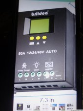
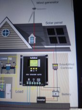
and the solar is controlled by separate controller connected to battery then, connected to GRID TIE ATS "as voltage monitor ONLY" it seems. !!! VERY SMALL BATTERY CONNECT INPUT TERMINALS!!!

I saw video tutorial that showed guy installing 3 prong L / N / G extension cords to each input, then tying all grounds together to inverter earth ground.

Also needing suggestion on an auto start generator wiring setup to wire into this ATS to auto start generator as low battery voltage AS GENERATOR WITH BE GRID INPUT IF THE 120V BATTERY AT GRID INPUT IS A NO...

THANKS FOR ALL HELPFUL SAFE TO DO INPUTS, HOMELESS GUY TRYING TO SURVIVE.
 

Attachments

  • 16957659207317472453353100457117.jpg
    16957659207317472453353100457117.jpg
    723.3 KB · Views: 0
  • 16957659962367200658954646587809.jpg
    16957659962367200658954646587809.jpg
    929.4 KB · Views: 0
Back
Top