


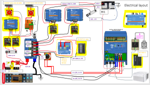
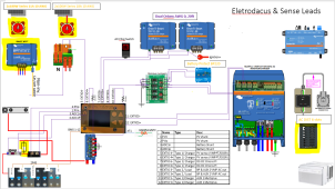
This is my first crack at electrical layout, I have a general power schematic and prettier Electrodacus/sense wire layout (discovered straight lines..) Building out an electrical supply system for my Sprinter Van I am DIY converting - pretty new to electrical systems so feel free to butcher anything
In case the pictures are not obvious the main system I have already purchased consist of
8 x 280 aH EVE cells wired in 2p4S which will yield 560aH @ 12V
Electrodacus BMS
Electrodacus DSSR PV solar controller
3000W/12V Victron Multiplus Invertor
Lyxn Distributor (don’t need the flashy light but got a bundled deal) – will add additional bus bar to extend connections
2 x “smart” 12/12/30 amp DC-DC Orions in Parallel
350A/100mV shunts
I think I will buy the following solar panels as I like the idea of low profile nature and if I ever get the urge I can use the van roof as a patio
Wire Lengths
In case the pictures are not obvious the main system I have already purchased consist of
8 x 280 aH EVE cells wired in 2p4S which will yield 560aH @ 12V
Electrodacus BMS
Electrodacus DSSR PV solar controller
3000W/12V Victron Multiplus Invertor
Lyxn Distributor (don’t need the flashy light but got a bundled deal) – will add additional bus bar to extend connections
2 x “smart” 12/12/30 amp DC-DC Orions in Parallel
350A/100mV shunts
I think I will buy the following solar panels as I like the idea of low profile nature and if I ever get the urge I can use the van roof as a patio
- 2x Alrska Flexible Solar Panel 100W 12V/24V Monocrystalline / each panel 5.34A Imp, 18.7V Vmp
- 2 x Alrska 180 Watt Flexible Solar Panel, 12 Volt Monocrystalline/ each panel 8.61A Imp, 20.9V Vmp
Wire Lengths
- Which wires have to be equivalent length +/-v – I get main wires to and from bus bars but what about to DC DC Chargers and MPPT/DSSR20?
- I have small gauge “ground” cables from Battery Protect/ DSSR/& Lynx Distributor that I assume I will find a convenient chassis point to attach to. What should I do with the Green Cable highlighted at the Multiplus – tie that to chassis ground it seems like its expecting a larger gauge wire
- Will be 2P4S,
- I have 3 additional “-ve/ground” connections that I was thinking I can extend the lynx with a dual bolt bus bar (for -ve need 2 from PV and one from BP which looks like a small “ground wire). For positive I need to small sense wire +ve so hoping I can just connect on top of one of the existing connections – my rational on position is the highest loads/inputs should connect closest to the main battery lug
- Eletradacus use the +ve side for measurements, a main battery shunt first of battery and then a PV shunt
- I undersized the main battery shunt as I was originally going 24V – I think I will replace with what I have (350A/100mV) with Victron Smart shunt 500A/50mV so that it can pull double duty talking to Victon and Electrodacus – I assume I can get the data from blue tooth wirelessly from the smart shunt but if I use a direct wire connection via VE direct do I have to do anything special ( some one mentioned it would need “fused sense wires” used on +ve line ..) - Worst case is I know I could add a third shunt on the negative side for just Cerbo but that introduces additional failure points and as its nice to have don’t wont do that
- Is having a fuse at Lynx distributer then a breaker and a further fuse at the chassis battery connection overkill or appropriate?
- I got a deal on two isolated DC-DC – I don’t intend to use them isolated so is there anything special I need to think about or do, could not seem to find any info except remove jumper
- I am really fuzy on the triggering for DC-DC Charger – What I want to do is have them turn on with ignition (so H input) and then additionally have the ability to turn them off (Switch on the L side ) – The BMS also uses the L connection to turn off the Orions.
- I have dual routes for PV charging though intend to always use both as i dont there is going to be excwss solar - hence I have not wired in a diversion circuit though i do have that version of DSSR. If there is an actual benefit from wiring either charge source parallel vs series knowing I also plan to buy a conventional MPPT. I plan to fit something like 600W on roof
- DSSR connections to panels don’t have a -ve connection – only a small ground wire,
- -ve return – As the way the electrodacus works they use a shunt on the positive side for battery and PV , So I need to provide -ve (ground though I appreciate that’s not what it is) – I can extend the negative bus bar from the Lynx distributer – obviously cable lengths are not going to be perfectly match
- Is switch the correct device on the Solar side of charger controllers as I planned to have breakers prior to these.
- As I only have two panels on each leg did not include fuses.
- I hope I can gang the sense/trigger wires for both the SSR and yet to be purchased MPPT – it seems that I have to use the VE direct if I pick Victron – I am assuming I can still collate Victron PV input via blue tooth
- I have read that getting 4/0 to fit on the Multiplus is a pain so figured I would run 2 x 2/0, for the short run post the switch was going to use a small length of 4/0
- I will plan to use trickle charging from Multiplus – I think the last I read I can wire +ve direct to EK1 (Maybe I can put a switch in line to disable this is I really need it ?
- I found a nice design for pre charge switch which I plan to use on the invertor switch – will be a dwell for a second at 1st position then connect – credit goes to filter guy at DIY solar.
- TBD probably panel from bluesea
Attachments
Last edited:
") Eight 280ah lifepo4 seems like a decent amount of storage already, but I know mobile can be hard to charge and space for more panels is often limited.
Eight 280ah lifepo4 seems like a decent amount of storage already, but I know mobile can be hard to charge and space for more panels is often limited.