


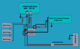
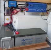
I have created a schematic for us to review and shared a photo of same.
I showed this schematic to a professional Solar Guru and he asked me to only move the Main Circuit Breaker to the just behind the Ceramic Fuse (as shown here), it was on the Main Negative wire to Inverter.
I have been helping a friend who purchased a van but the installation was sub-par and actually dangerous for a few big reasons.
I have now 100% completely re-done the Solar Panels (now 600 Watts @ 36 volts), MPPT, Inverter/Charger, Battery layout, Voltage Sensitive Relay, Shore Power Feed (loose arcing wires !!), DC Power Fuse Box, and all the AC & DC wiring.
The picture shown depicts the image except I added the chassis ground wires from the MPPT and the Inverter/Charger since I took the photo.
Is there anything I'm missing or should consider changing?
Thanks gang.
Attachments
Last edited:
")