You are using an out of date browser. It may not display this or other websites correctly.
You should upgrade or use an alternative browser.
You should upgrade or use an alternative browser.
Safety check on my simple diagram please
- Thread starter Travis55
- Start date
Bluedog225
Texas
- Joined
- Nov 18, 2019
- Messages
- 2,917
I was under the impression that the fuse should be the first stop from the battery. Others will know.
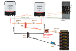
Thanks! So instead of the two - 200A class T fuses, I would just need one fuse. Since it's in line on the 4/0 cable right off the battery bank would it need to be higher amperage then?fuse should go between batteries and the switch. First disconnect after meter should be bonded.
I don't see communication in this, but assuming that's implied.
For communication, that would be the serial cable running between the two inverters and then having them set to the correct phasing I believe?
Looking over the manual, they should communicate with the batteries as well. So the sync cable and battery comms.
153 amp is the expected draw according to the manual as well, so 200a fuse is likely fine. 4/0 is likely overkill, but leaves you room to add more inverter without rewiring. Just have to change the fuse.
153 amp is the expected draw according to the manual as well, so 200a fuse is likely fine. 4/0 is likely overkill, but leaves you room to add more inverter without rewiring. Just have to change the fuse.
OffGridForGood
Catch, make or grow everything you can.
cable sizes all check out.
two 6548's = 13,000W
at 48 volts you could draw up to 270A from the ESS,
I would put a 300 or 350 A Class T fuse between the ESS and the DC disconnect.
I would put a 500A Victron Shunt between the ESS and the small bus Negative,
I would put Solar Assistant between the two inverters and connect all comms to SA.
Thanks for mathing. I apparently need sleep and forgot to double the load.cable sizes all check out.
two 6548's = 13,000W
at 48 volts you could draw up to 270A from the ESS,
I would put a 300 or 350 A Class T fuse between the ESS and the DC disconnect.
I would put a 500A Victron Shunt between the ESS and the small bus Negative,
I would put Solar Assistant between the two inverters and connect all comms to SA.
Would that be total between the two inverters? I wasn't sure if that 153 stacks and becomes 306 from both of them drawing for split phase.Looking over the manual, they should communicate with the batteries as well. So the sync cable and battery comms.
153 amp is the expected draw according to the manual as well, so 200a fuse is likely fine. 4/0 is likely overkill, but leaves you room to add more inverter without rewiring. Just have to change the fuse.
OffGridForGood
Catch, make or grow everything you can.
That is why we double check each other, best to get a second opinion rather than a problem later.Thanks for mathing. I apparently need sleep and forgot to double the load.
OffGridForGood
Catch, make or grow everything you can.
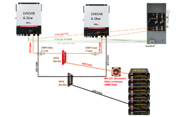
Each inverter will draw up to 6500/48 = 135A from the ESS (battery bank) but they add since both tie into the small bus pos and neg.Would that be total between the two inverters? I wasn't sure if that 153 stacks and becomes 306 from both of them drawing for split phase.
The cable from the battery bank to the bus may carry double ie 270A (maybe a bit more if the inverters can take some over load to start up a motor or some other big inductive load)
A fuse on the main battery cable should be capable of 300A, a 350A may be a better choice. Put the fuse As Close As Possible to the battery end.
After the small bus, you could put a 200A class T to each inverter. not really necessary, but adds some protection in case of something bad happens.
Thanks, here's the updated diagram with those edits if I understood correctly. What about the bonding of neutral/ground on the transfer switch?Each inverter will draw up to 6500/48 = 135A from the ESS (battery bank) but they add since both tie into the small bus pos and neg.
The cable from the battery bank to the bus may carry double ie 270A (maybe a bit more if the inverters can take some over load to start up a motor or some other big inductive load)
A fuse on the main battery cable should be capable of 300A, a 350A may be a better choice. Put the fuse As Close As Possible to the battery end.
After the small bus, you could put a 200A class T to each inverter. not really necessary, but adds some protection in case of something bad happens.

OffGridForGood
Catch, make or grow everything you can.
And Solar Assistant set between the two MPP 6548's - trust me you will be glad you have Solar Assistant to monitor the system, and make changes from your phone or a lap-top.
ONE N-G bond in a system - only one!
There are posts on the forum discussing the N-G bonds in various inverters, since some create a N-G bond internally only during inverting mode. In some inverters this is done with a relay and can be programed to not do it - ie if tied to a main system as I suspect you are.
In my MPP 6048's there is no program option, but they make the bonding screws easily removable with a screwdriver. I have all the MPP N-G bonds removed from mine and use a common N in the system.
This may not be the best option for your set up.
I don't know enough about your set up or the 6548 to tell you what you need to do with the ground-N
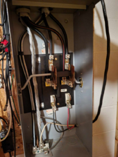
I do know to ask one thing - that transfer switch you are showing/planning - it is switching 2 conductors - L1 L2 or three conductors L1 L2 & N ?
Last edited:
@OffGridForGood
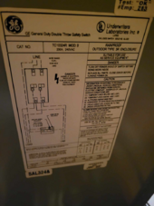
This is how it's set up right now, I just moved into the place last year, and the transfer switch was already installed. I assume the Red and Black LINE on the bottom + the Neutral and Ground go out to a generator hookup, which is what I was going to sub out with my inverter/battery bank setup.


This is how it's set up right now, I just moved into the place last year, and the transfer switch was already installed. I assume the Red and Black LINE on the bottom + the Neutral and Ground go out to a generator hookup, which is what I was going to sub out with my inverter/battery bank setup.


OffGridForGood
Catch, make or grow everything you can.
I would like to call in an expert - @timselectric will be able to explain this best.
Similar threads
- Replies
- 2
- Views
- 257
- Replies
- 7
- Views
- 292
- Replies
- 23
- Views
- 865
- Replies
- 21
- Views
- 905


