diy solar

diy solar

Solark 15k wiring 200amp bypass switch

BlueMarblePA

Solar Enthusiast
Joined
Sep 11, 2022
Messages
419
Location
PA
I finished installing diy a grid tie 7.6kw solaredge used system with 40amp back feed breaker and 9.8kw pv. With the help of this forum, I received PTO in April 2023.

Now, I want to install a solark 15k so that I can add more pv to the system and batteries and have backup should the grid go down. I received a quote from a reputable dealer for $14k just to install the solark without a bypass, without batteries and without additional pv. Seems like $7k for the inverter and $7k in labor plus miscellaneous parts.

I am trying to figure how to do this myself. I have 400amp service CL320 with double lug split to two 200amp panels in the basement sitting side by side. I only need one of the 200amp panels in a grid down situation. Hence, this one panel is the one I want to have a solark 15k.

I don't have experience pulling a meter from the service entrance, and I am sure my POCO would not approve. But I know the $14k quote specifically says that since we are not upgrading the solar pv panels, they are just going to pull the meter themselves and install.

My question after studying the wiring diagram from solark is how to split the 240v 4/0 service entrance cable after the fused disconnect? It seems that the line voltage can go to the LINE IN of the solark 15k and the Line side of the 200amp manual bypass switch.

I am thinking of hiring an electrician just to wire the fused disconnect and the double pole 200amp three way disconnect, so that I can just buy the solark 15k myself and save some cash.

Your help with pictures would be greatly appreciated? Do I just put a double lug at the fused disconnect?

Also which box becomes the neutral to ground bond? I assume it is no longer the main electrical panel, since the first means of disconnect is now the fused disconnect
 

Attachments

  • Screenshot_20230718-170747_Adobe Acrobat~2.jpg
    Screenshot_20230718-170747_Adobe Acrobat~2.jpg
    110.9 KB · Views: 84
The minimum install would be to take the feed into the 200 amp panel, and route that to the Grid Input of the Sol-Ark. The Load Output of the Sol-Ark would then feed the 200 amp panel.

More complex is to add transfer switches to take the Sol-Ark out of the circuit, incase you need to do something to it.

If your total PV is 15kW or less, then see if you can move all of the PV to the Sol-Ark. Otherwise, the recommended installation is to have the Solaredge come in the Gen Input of the Sol-Ark.

If you want the line splitter, something like this:

However, with a line splitter, you still have Grid power to the Sol-Ark if you need to work on it. With a 2nd Transfer Switch, the grid power is disconnected.
 
Last edited:
The minimum install would be to take the feed into the 200 amp panel, and route that to the Grid Input of the Sol-Ark. The Load Output of the Sol-Ark would then feed the 200 amp panel.

More complex is to add transfer switches to take the Sol-Ark out of the circuit, incase you need to do something to it.

If your total PV is 15kW or less, then see if you can move all of the PV to the Sol-Ark. Otherwise, the recommended installation is to have the Solaredge come in the Gen Input of the Sol-Ark.

If you want the line splitter, something like this:

However, with a line splitter, you still have Grid power to the Sol-Ark if you need to work on it. With a 2nd Transfer Switch, the grid power is disconnected.
1. Minimum install seems like you have to decrease amperage as the grid in to the solark 15k would have to go through a 100amp breaker for example and the load out from the solark would have to back feed the 200amp panel? Not sure if this is what you meant.

2.definitely want to do transfer switches but it seems I need two transfer switches.

3. I can definitely move the solaredge 9.8kw pv with solaredge rooftop panel optimizers out of my second panel into the solark 15k through the Gen input. I have future plans for additional solar pv via ground mount.

4.thank you for the link. I used Polaris plugs in one of my rooftop junction boxes, and so I could just do this, but exactly as you said, I was confused because it would bring Grid Line in live through Polaris into the Solark all the time without a way to disconnect.

5. Hence we are now back to two disconnects plus a bypass. The first is a fused 200amp disconnect directly from the meter to disconnect everything from the grid. Put the Polaris lug here so that current can go to either three way bypass switch and to the solark grid input. Add a Second fused or maybe nonfused 200amp disconnect between the first disconnect (Polaris lug) to the solark 15k grid in. This is drawn in purple in this picture. This allows me to disconnect the solark from the grid line voltage. Then include the three way bypass switch which allows me to bypass the solark so that grid can feed the loads.

Hence I need three additional pieces of equipment in addition to the solark 15k? Seems like I am over complicating it?
 

Attachments

  • Screenshot_20230718-170747_Adobe Acrobat~3.jpg
    Screenshot_20230718-170747_Adobe Acrobat~3.jpg
    110.4 KB · Views: 41
1. Minimum install seems like you have to decrease amperage as the grid in to the solark 15k would have to go through a 100amp breaker for example and the load out from the solark would have to back feed the 200amp panel? Not sure if this is what you meant.

2.definitely want to do transfer switches but it seems I need two transfer switches.

3. I can definitely move the solaredge 9.8kw pv with solaredge rooftop panel optimizers out of my second panel into the solark 15k through the Gen input. I have future plans for additional solar pv via ground mount.

4.thank you for the link. I used Polaris plugs in one of my rooftop junction boxes, and so I could just do this, but exactly as you said, I was confused because it would bring Grid Line in live through Polaris into the Solark all the time without a way to disconnect.

5. Hence we are now back to two disconnects plus a bypass. The first is a fused 200amp disconnect directly from the meter to disconnect everything from the grid. Put the Polaris lug here so that current can go to either three way bypass switch and to the solark grid input. Add a Second fused or maybe nonfused 200amp disconnect between the first disconnect (Polaris lug) to the solark 15k grid in. This is drawn in purple in this picture. This allows me to disconnect the solark from the grid line voltage. Then include the three way bypass switch which allows me to bypass the solark so that grid can feed the loads.

Hence I need three additional pieces of equipment in addition to the solark 15k? Seems like I am over complicating it?
I guess I made it too complicated. If I ever need to disconnect the solark and don't want to work on live voltage, I just shut off the 200amp fused disconnect and then disconnect the cable from the Polaris connectors so that no current will go to the solark.

I think like the drawing shown here.

 
@Chickenstick drawing helps me to understand. Basically I need a junction box with polaric lugs after the 200amp fused disconnect
 

Attachments

  • Screenshot_20230719-141647_Chrome.jpg
    Screenshot_20230719-141647_Chrome.jpg
    163.5 KB · Views: 79
There is also this link
 
@Chickenstick drawing helps me to understand. Basically I need a junction box with polaric lugs after the 200amp fused disconnect
@BlueMarblePA

Did you end up using the Polaris Lugs as shown in the attachment? I'm trying to something very similar and posted a question about it in another thread - here. I basically proposed what you did with the Polaris lugs using the grid power to split / feed the inverter as well as one side of the bypass switch at the same time. Alternatively, I was wondering if I needed to feed the inverter from a separate double pole breaker.
Installation with polaris lugs should be happening next week. I hired an electrician to pull meter and add manual transfer switch. I take delivery of the Solark 15k today (purchased from Johnny Valentine from Gain Solar). I am making progress.
 
Polaris lugs are one method. One Johnny recommends and is a bit easier to manage IMhO are Power Distribution Blocks or PDB’s. Reason being that the lugs just float in the junction box or wiring gutter on the ends of the wires and aren’t tied down. The PdB’s are affixed to the wall of the enclosure and are much like inserting the cable into any other lug. That and you can get them in sets of 3 for your two hots and neutral so things are all neat and tidy instead of a jumble of wires tied at the ends.

Look at this product for ~$70
MPDB674231Ferraz Shawmut MPDB Series Intermediate Aluminum Power Distribution Block, 380A, 3-pole, 1 hole line side (in) 500-#4, 2 holes load side (out) 4/0-#6**Replaces 67423**
 
Installation with polaris lugs should be happening next week. I hired an electrician to pull meter and add manual transfer switch. I take delivery of the Solark 15k today (purchased from Johnny Valentine from Gain Solar). I am making progress.
We put in double lugs at meter panel.

1 set lugs goes to transfer switch input A side Grid
1 set lugs goes to Fused disconnect then to inverters.

Instead of using double lugs at the meter pan you can cut the wire coming into the house to your AC panels.
Install a pass through 2 port Polaris.
One to Transfer and 1 to inverters.

Interesting you bought from Johnny.

I bought stuff from Scott but never Johnny.
So you have a non fused, non protected run of your 200a service open to your grid side supply?

Why have one set of mains protected and one not?

If you were going to double lug something I would think it would be the feed side of the fused safety switch, that way both sets of mains would be protected and you could still route them as you described after the switch.
What?

We have 1 connection from meter lug to Service entry rated Transfer switch input.

Other side of meter lug goes to a Fused disconnect then to inverters.

Where is the issue?
 
What?

We have 1 connection from meter lug to Service entry rated Transfer switch input.

Other side of meter lug goes to a Fused disconnect then to inverters.

Where is the issue?
The first connection you list isnt protected (via a fuse) by your transfer switch. Utility power flows directly from the source to your loads beyond the transfer switch.

It’s not a problem per se, I was just wondering why, since you took the trouble and expense of installing a fused safety switch, why main power didn’t go thru it and thereby gain the protection of having all your power supply go thru those fuses, and then split to your load feeds.

Around here, especially on grid tie systems, the power Company insists on, and I believe newer code dictates, that the first device past the meter is a fused safety switch. Beyond that is where all other splits, connections, transfer switches and connections to inverters and loads take place. The theory is to protect everything on the customer side of the meter from harmful spikes from the supply side as I understand it.
Because if I have to turn off the grid to the inverters I won’t have any Grid for the house is why.

If I split it after the Fused disconnect then every time I turn it off to the inverters I would have nothing to run to the House.

Every Service entry rated transfer switch I have ever seen has a live connection to the meter pan.
Hence Service entry rated switch.

The first device past the meter is your N-G bond.

Transfer switch input A Grid, input B Inverters.
Load: house and shop.

There are 200 amp breakers in the distribution panels.

This was inspected by county inspectors with NEC 2017 so not sure what to say.
 
Last edited:
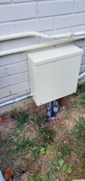
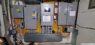
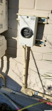
Electrician did a great job of replacing the old Cahllenger panel with a new Siemens panel (separating neutral and ground) as the new first point of disconnect is outside. They installed the 200amp manual transfer switch and connected the Solark, using the Polaris plugs. Unfortunately, I found out about the power distribution blocks too late.

Unfortunately, they installed a 200amp circuit breaker outside as the first means of disconnect rather than a 200amp fused disconnect. I pointed out that the wiring diagram and the contract called for a fused disconnect. Ultimately, they agreed with me, and they are supposed to be replacing the smaller 200amp breaker with a 200 amp fused disconnect outside.

In the left of the picture, you can also see my PV wires (8AWG green and 10AWG black/red x 2) that I brought from the trench into a junction box and transitioned from PVC to EMT and then looped it to the IMO close to service entrance and back to the junction box. Then, I transitioned to EMT through basement crawl space inside house to the basement 20231026_164407.jpg20231027_055305.jpg20231022_170129.jpg
 

Attachments

  • 20231027_055305.jpg
    20231027_055305.jpg
    1.3 MB · Views: 15
Back
Top