plr
New Member
- Joined
- Sep 21, 2019
- Messages
- 66


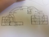
You need to wire them like this...minimally...
What maximum voltage can your inverter accept?View attachment 15444
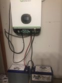
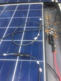
So there is no voltage on the panel wires at the Growatt?Did I wire wrong for 3S4P? I have 48v growatt with 24v panels. I attached my crude wiring diagram and pic of my panels
No Volts measured where?Thanks yeah I changed the growatt settings to CSO and OSObut still got the same thing no volts
Disconnect the 2 panel wires from the Growatt and read the short circuit voltage with a meter or put the probes on the connections.Sorry again...I see no PV watts on my growatt