diy solar

diy solar

Terminals on 304AH cells are these too small for 300Amps?

opi

New Member
Joined
Feb 15, 2020
Messages
15
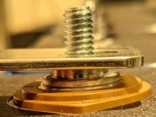
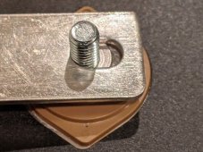
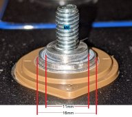
Just received 64 EVE 304AH cells and welded to the positive and negative terminals are M6 posts/studs on an 11mm base. (see images below)
The issue I'm concerned about is that the base is only a few mm thick at best and placing the busbar provided for interconnects over top of it doesn't give me much comfort that there's enough contact surface to adequately transfer and sustain up to 300 amps of current from the terminal through the post and across the bus bars back to the next terminal.

What could be done to help ease my concerns or should I be OK with this?
terminal4.jpg
terminal1.jpg
terminal2.jpg
 
I've hated those terminals for this reason. Stock terminal with Internal threads and a grub screw for me, thanks.

Anyway, assuming you use 60% of the available surface area adjacent the thread for contact with the bus bar, that's 40mm^2

That's almost the equivalent of 1awg. Since there's no insulation on it, the amount of current it can handle is pretty nutso.


Lists 1awg marine wire capable of 245A - again, that's insulation based. Fusing of 1awg is 1600A, so you're well under that.

Normally, I just consider the contact surface of the two faces in direct contact as a conservative approach. In a situation like this, I consider that there are also threads, a washer and a nut that all add to the surface area even if they're not as good as copper. This surely pushes you up another 50A to hit your 300A.

It will work, but at 300A sustained, you're likely going to see some heat.

You should also compute the cross section of the bus bar itself. Guessing those are 3mmx15mm or so... that's only 45mm^2 - not much bigger than the contact surface.
 
My first question would be if you actually need to pull 300a.

Surge loads don't really have a huge impact unless they're way higher than "normal". Sustained 300a is a ton of power and warrants considering a higher voltage pack anyways.
 
My first question would be if you actually need to pull 300a.

Surge loads don't really have a huge impact unless they're way higher than "normal". Sustained 300a is a ton of power and warrants considering a higher voltage pack anyways.

Erm, good point. I just focused on the 300A number.

64 cells = 4P16S LFP?

IF the current plan is a 4P16S battery, heck no. Break it up into 4X 16S each with its own BMS. Then you have ~75A through each bus bar.
 
It looks like my concerns have already been addressed in a prior thread:
https://diysolarforum.com/threads/c...fepo4-cell-manufacturing-design-change.24969/
and tested here:
https://diysolarforum.com/threads/r...ure-cells-from-shenzhen-luyuan-amy-wan.22371/
So my initial concerns are now much less acute.

My plan is to run these cells off a 12,000 watt 48v inverter which would draw 250 Amps if it hit the 12K watt mark though I think in my situation that would be the exception and not a common occurrence. I do want to account for surge pulses of up to 300 Amps and the cells themselves can handle pulses up to 2C or 600 Amps so I was hopeful the skinny looking terminals wouldn't hinder this ideal.

The seller did confirm that they've tested 200A continuous output without a problem using these studs and busbars so even though the look of them is much to be desired, the picture appears to be OK for what is needed.
 
Erm, good point. I just focused on the 300A number.

64 cells = 4P16S LFP?

IF the current plan is a 4P16S battery, heck no. Break it up into 4X 16S each with its own BMS. Then you have ~75A through each bus bar.

What about this ^ ?

A 4P16S battery will have to pass the 300A through the bus bars. 4X 16S batteries will only pass ~75A. Additionally ONE BIG BATTERY with parallel cells has zero redundancy, and a single cell failure is a huge hassle to track down and maintain functionality. 4X 16S batteries in parallel have all 64 cells individually monitored. Cell fails, disconnect the one battery, still have 3 running.

IMHO, the convenience and redundancy are worth the price of the additional BMSs.

It looks like my concerns have already been addressed in a prior thread:
https://diysolarforum.com/threads/c...fepo4-cell-manufacturing-design-change.24969/
and tested here:
https://diysolarforum.com/threads/r...ure-cells-from-shenzhen-luyuan-amy-wan.22371/
So my initial concerns are now much less acute.

My plan is to run these cells off a 12,000 watt 48v inverter which would draw 250 Amps if it hit the 12K watt mark though I think in my situation that would be the exception and not a common occurrence. I do want to account for surge pulses of up to 300 Amps and the cells themselves can handle pulses up to 2C or 600 Amps so I was hopeful the skinny looking terminals wouldn't hinder this ideal.

The seller did confirm that they've tested 200A continuous output without a problem using these studs and busbars so even though the look of them is much to be desired, the picture appears to be OK for what is needed.

As @Short_Shot mentioned, surge currents are generally not considered.
 
Back
Top