diy solar

diy solar

Victron BMV-712 Smart Battery monitor

MountainmanBill

New Member
Joined
Feb 20, 2021
Messages
69
I don't get it, or, what am I missing? Looking at the manual for this device it states:

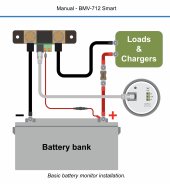
3.5. Basic electrical connections Connection procedure: 1. Connect the negative battery terminal to the M10 bolt on the "BATTERY ONLY" side of the shunt. Tighten the shunt bolt with a maximum torque of 21Nm. Note that there should be no other connections on this side of the shunt or on the negative battery terminal. Any loads or chargers connected here will be excluded from the battery state of charge calculation.

For one thing, my battery terminals have a 3/8" stud that will not accept that little 10mm wire terminal provided with the shunt. For another, that little wire that goes from the negative battery terminal is no way going to support all the amps going out of the batteries and to the inverter. My inverter has to have a 1/0 cable to perform adequately so things aren't adding up, or I just understand what's going on here. Help in the understanding of this device would be greatly appreciated.
 
The littler wire goes to positive. The big bolts with nuts are for the cable to connect the negative wire between the battery and inverter.
 
But it says in the manual, as stated in my first post: "Connection procedure: 1. Connect the negative battery terminal to the M10 bolt on the "BATTERY ONLY" side of the shunt." It doesn't mention "Big bolts". So should I assume that the gold bolts in the diagram provide by RV8er in post #2 are 10mm bolts. Not so? Even though it says they are in the manual? Perhaps there are two sets of bolts on the shunt. A 10mm bolt and a larger one to except a larger cable from the battery negative?

And if the "little wire" goes to the positive battery post, I'll need an adapter of some sort to go from the 3/8 stud on the battery to a 10mm terminal of the little wire, correct?
 
I don't get it, or, what am I missing? Looking at the manual for this device it states:

3.5. Basic electrical connections Connection procedure: 1. Connect the negative battery terminal to the M10 bolt on the "BATTERY ONLY" side of the shunt. Tighten the shunt bolt with a maximum torque of 21Nm. Note that there should be no other connections on this side of the shunt or on the negative battery terminal. Any loads or chargers connected here will be excluded from the battery state of charge calculation.

For one thing, my battery terminals have a 3/8" stud that will not accept that little 10mm wire terminal provided with the shunt. For another, that little wire that goes from the negative battery terminal is no way going to support all the amps going out of the batteries and to the inverter. My inverter has to have a 1/0 cable to perform adequately so things aren't adding up, or I just understand what's going on here. Help in the understanding of this device would be greatly appreciated.
Correct me if I’m wrong but I’m thinking that you don’t actually have the shunt or looked at it and are just reading he manual. I’m more than happy to help you.

The shunt has a battery side and a load side. There are two 10mm terminals on the shunt. They are the big brass bolts on either side. Now I’m unsure whether you are familiar with both metric and imperial but 3/8th of an inch is equal to 9.525mm, in other words the 10mm bolts are larger than your 3/8th terminal bolts.

All you need to do in your current set up is cut your 1/0 negative cable close to your battery and crimp a 10mm ring terminal each end. Connect from your battery to the battery side of the shunt and then from your load side of the shunt to all your loads.

The only cable that comes with the shunt is a thin red sensor wire which clips into the shunt and is connected to your positive terminal. I’m unsure of the size of the ring terminal on this but it may well be that you will need an adaptor to connect to your positive terminal.

Hope this helps.
I have a stand-alone battery that I use for another purpose that I have to use a 10mm wrench on. I do believe that's where my confusion was. The bolt's head diameter vs its thread diameter. Thanks for clearing that up for me.

And you are correct in assuming I didn't have the unit in front of me. I had ordered one and was reading the manual in anticipation of its arrival. Thanks again.
 
Another question since y'all seem to have this down. Concerning he second red wire that goes to the shunt's +batt2 port. The manual says I can monitor the battery bank's midpoint so the system can monitor both halves of the bank for any discrepancies between the two.

I have 8- 6-volt 400Ah batteries wired in series for 48 volts. I would put the +batt2 red wire on the 4th (or 5th?) battery's positive post for this function to operate correctly? Is this correct?
 
Don't take the bolt size too literally.

You should always use a cable lug hole size appropriate for the terminal post size. Connection resistance is surface to surface area compression so you don't want to use a cable lug hole much larger than terminal post size as it reduces surface to surface contact area.

Victron shunt has 10 mm bolt size so that is their reason for the statement.

Most all metric cable lug hole sizes stay compatible with SAE lug hole size dimensions.
A 3/8" lug hole fits on a 10 mm bolt thread.

The positive wire is only for battery voltage monitoring and powering the display module. You usually want the monitor's readout voltage to represent the battery voltage as close as possible so connect it on battery positive terminal, on top of high current lug, to avoid inverter high battery cable current voltage drop on a long positive cable. It is a good idea to put a low amperage (1/2 amp) inline fuse on the positive monitor wire.

You should connect shunt close to negative battery terminal with short negative high current cable between battery negative terminal and shunt to avoid too much voltage drop on that cable as it will affect monitor voltage reading. If you have parallel batteries make sure you use large enough gauge on combining negative battery connections before shunt to avoid too much voltage drop on negative side battery cables to shunt.

The monitor measures voltage after any BMS, so BMS negative path voltage drop will affect monitor voltage reading. A good setup is less than 0.1 vdc effect on monitor voltage reading under high inverter load current.
 
Last edited:
Is it even necessary to mount or even use the display screen that comes with the unit since everything can be seen and controlled via a smart phone?
 
Is it even necessary to mount or even use the display screen that comes with the unit since everything can be seen and controlled via a smart phone?
BMV-712 is not like smart shunt. The controller and BT link is in the display module.

The 712 actual shunt is just a wiring connections junction with some interface connectors.

You can use BMV-712 display module with a plain-old 500A/50mV shunt with a little extra wiring for battery voltage line.
 
Last edited:
Back
Top