diy solar

diy solar

Why do we use a PV disconnect that breaks both the positive and negative side of a PV circuit?

It's only a situation with AIO's, as far as I know.

Yes, that would be a dead short.
Then I guess over current protection is required on the pv side regardless of the number of pv strings.

I wonder if pv.negative and bat.negative are common?
 
Then I guess over current protection is required on the pv side regardless of the number of pv strings.

I wonder if pv.negative and bat.negative are common?
Pv panels are primarily a current source not a voltage source ( like a battery ) , pv ps else are not sun powered batteries actually , they are sun powered current sources.

Current sources can happily be shorted with no effects. ( well assuming your pv cables are rated to Isc )
 
just didn't think I'd need to with turning the panels off and it being almost dark, and then found out the hard way in regards to the back feeding of those inverters.
I got lucky that i didn't have to find out the hard way because i noticed one of my Growatt SPF5000's would show ~80v on the pv in total darkness, but it would go away if i turned off the solar disconnect. Given the voltage and the fact that it went away from turning off the solar disconnect, i figured it HAD to be AC present all the time that just wasn't showing on the DC volts counter, but it would appear as DC after passing through the bypass diodes of the panels. I actually still never put a meter to it to see the actual AC voltage level present. 80 is pretty close to half-wave rectified 120v, but the Growatt doesn't put out 120 internally anywhere that i'm aware of, so might be a coincidence. I do have an autotransformer but I can't visualize a path back to the inverter that would involve that, and i think i turned it off with no change.

My other identical growatt in parallel does not do this.

But i haven't said anything about it because i'm assuming it's my fault. I've done.. 'things' to my inverters that are not recommended, and unless i can be very sure that a problem i'm having has nothing to do with the experiments i've done, i'm not going to go pissing and moaning on the internet about it because a whole bunch of people will just add it to their 'growatt skepticism' file before it's eventually proven out that IM the one who messed it up. It's not Growatt's fault i do weird things in the closet. My electrical closet, that is.
 
Back in the days when I worked for a sign company it wasn't unusual at all to get a jolt from a neutral wire. Super annoying but it happened often.
 
I got lucky that i didn't have to find out the hard way because i noticed one of my Growatt SPF5000's would show ~80v on the pv in total darkness, but it would go away if i turned off the solar disconnect. Given the voltage and the fact that it went away from turning off the solar disconnect, i figured it HAD to be AC present all the time that just wasn't showing on the DC volts counter, but it would appear as DC after passing through the bypass diodes of the panels. I actually still never put a meter to it to see the actual AC voltage level present. 80 is pretty close to half-wave rectified 120v, but the Growatt doesn't put out 120 internally anywhere that i'm aware of, so might be a coincidence. I do have an autotransformer but I can't visualize a path back to the inverter that would involve that, and i think i turned it off with no change.

My other identical growatt in parallel does not do this.

But i haven't said anything about it because i'm assuming it's my fault. I've done.. 'things' to my inverters that are not recommended, and unless i can be very sure that a problem i'm having has nothing to do with the experiments i've done, i'm not going to go pissing and moaning on the internet about it because a whole bunch of people will just add it to their 'growatt skepticism' file before it's eventually proven out that IM the one who messed it up. It's not Growatt's fault i do weird things in the closet. My electrical closet, that is.

If I'm not mistaken everyone else that I've seen across the threads and talked to via other channels, has gotten shocked when touching their panels. If someone else's mileage was different, I'm curious to know. In the other thread I posted readings from my multimeter for various scenarios like Panels off, Battery bank connected; Panels off, Battery Bank Disconnected, Panels off, Battery Bank Disconnected, AC Input disconnected, and Panels off, DC Disconnect disconnected. When the panels were off and I had my wife cut connectivity via the DC Disconnect, the voltage immediately dropped. In all of the other scenarios, there was voltage potential between the Ground wire from the panels (that goes to the GEC) and the PV wires from the inverter.

I got more readings last night from the inverter side if anyone is interested, showing voltage between PV input and the Battery Pos and Neg, PV input and the Ground, and others. I still don't exactly know what's going on / how I got shocked from the ground wire.
 
It sounds like you've already done what i need to be doing! I'll have to go find the other thread and read up. I'm very interested in the numbers.

And i'll also be happy with any information that leads to me to believe that some of the weird stuff i've seen on my system is not, in fact, my own fault. ?
 
Because of the non-isolated PV inputs from PWM AC chopper, there has been cases of accidentally allowing a PV line wire to momentarily touch ground and blowing out inverter sinewave PWM IGBT AC output power devices.

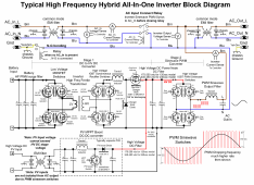
When HF inverter has its AC neutral grounded and AC inverter is active, the internal HV DC bus supply ground reference is chopped at AC line frequency between HV DC positive and negative sides of HV DC supply. When PV SCC controller is not electrically isolated its negative terminal will follow this HV DC ground reference switching. The PV electrolytic filter capacitors will cause positive terminal on PV to follow this chopping so both pos and neg lines on PV will ride on top of this HV DC ground reference polarity chopping.

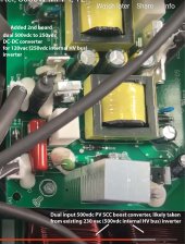
Some HF inverters have an extra transformer coupled DC-DC converter between PV SCC output and inverter's HV DC supply. This extra DC-DC converter provides electrical isolation between inverter HV DC and PV inputs. It is usually done to allow maximum PV DC input voltage to be higher than inverter internal HV DC supply, typically so a 120vac inverter with 250v HV DC bus supply can allow PV inputs up to 500vdc. The extra DC-DC converter steps down SCC 500vdc output to inverter's 250vdc internal HV DC bus. Isolation is just a nice side benefit. Example of this extra DC-DC converter can be found on EG4 6500 EX-48 inverter. It has the extra DC-DC converter on top of 500vdc PV SCC PCB board for a 120 vac inverter to allow 500vdc max PV inputs.

HF inverter block diagram.png

Picture of EG4 6500 extra DC-DC converter in PV power path.
EG4 6.5kVA inverter SCC.jpg
 
Last edited:
Because of the non-isolated PV inputs from PWM AC chopper, there has been cases of accidentally allowing a PV line wire to momentarily touch ground and blowing out inverter sinewave PWM IGBT AC output power devices.

When HF inverter has its AC neutral grounded and AC inverter is active, the internal HV DC bus supply ground reference is chopped at AC line frequency between HV DC positive and negative sides of HV DC supply. When PV SCC controller is not electrically isolated its negative terminal will follow this HV DC ground reference switching. The PV electrolytic filter capacitors will cause positive terminal on PV to follow this chopping so both pos and neg lines on PV will ride on top of this HV DC ground reference polarity chopping.

Some HF inverters have an extra transformer coupled DC-DC converter between PV SCC output and inverter's HV DC supply. This extra DC-DC converter provides electrical isolation between inverter HV DC and PV inputs. It is usually done to allow maximum PV DC input voltage to be higher than inverter internal HV DC supply, typically so a 120vac inverter with 250v HV DC bus supply can allow PV inputs up to 500vdc. The extra DC-DC converter steps down SCC 500vdc output to inverter's 250vdc internal HV DC bus. Isolation is just a nice side benefit.

View attachment 109203

You just blew my mind. ?
 
This is exactly the kind of stuff i wish i could just easily figure out without having to ask 'why am i being electrocuted' as the lead in.

Thank you for taking the time to put that out here.
 
Because of the non-isolated PV inputs from PWM AC chopper, there has been cases of accidentally allowing a PV line wire to momentarily touch ground and blowing out inverter sinewave PWM IGBT AC output power devices.

When HF inverter has its AC neutral grounded and AC inverter is active, the internal HV DC bus supply ground reference is chopped at AC line frequency between HV DC positive and negative sides of HV DC supply. When PV SCC controller is not electrically isolated its negative terminal will follow this HV DC ground reference switching. The PV electrolytic filter capacitors will cause positive terminal on PV to follow this chopping so both pos and neg lines on PV will ride on top of this HV DC ground reference polarity chopping.

Some HF inverters have an extra transformer coupled DC-DC converter between PV SCC output and inverter's HV DC supply. This extra DC-DC converter provides electrical isolation between inverter HV DC and PV inputs. It is usually done to allow maximum PV DC input voltage to be higher than inverter internal HV DC supply, typically so a 120vac inverter with 250v HV DC bus supply can allow PV inputs up to 500vdc. The extra DC-DC converter steps down SCC 500vdc output to inverter's 250vdc internal HV DC bus. Isolation is just a nice side benefit. Example of this extra DC-DC converter can be found on EG4 6500 EX-48 inverter. It has the extra DC-DC converter on top of 500vdc PV SCC PCB board for a 120 vac inverter to allow 500vdc max PV inputs.

View attachment 109203

Picture of EG4 6500 extra DC-DC converter in PV power path.
View attachment 109215
I'm still studying this - probably take me a few days to wrap my head around it, but definitely appreciate it! :)
 
Can this behvaviour be replicated with a decent standalone solar charge controller, like Victron for instance?
There's no voltage from a Victron standalone charge controller otherwise I would have been shocked several times :sneaky: And the Midnite surge protector on the arrays have a blue led which would show any voltage on the line.
 
A direct to battery PV charge controller does not have this issue.

On a HF AIO inverter that is not isolated, if you hook a scope between neutral ground and negative PV lead you will see about a 250-280v square wave for 120vac inverter or 350-380v square wave on 230vac inverter at AC line frequency rate. Just make sure you use a 10x probe that can take the maximum input voltage.
 
Last edited:
There's no voltage from a Victron standalone charge controller otherwise I would have been shocked several times :sneaky: And the Midnite surge protector on the arrays have a blue led which would show any voltage on the line.

I have confirmed with a multimeter, no voltage come out of my Victron SCC's on the PV inputs, but I only tested that on a 12v battery bank implementation.
 
Yeah, I actually have an IMO DC Disconnect down by the inverters and one in the Soladeck on the roof that disconnect both conductors - just didn't think I'd need to with turning the panels off and it being almost dark, and then found out the hard way in regards to the back feeding of those inverters.

When in doubt, it's good practice to get in the habit of always confirming with the good 'ol multimeter... I have been electrocuted once pretty darn well (not an understatement, I can really say after that, I have a full understanding of electricity now from the perspective of being a human oscilloscope), and never been electrocuted ever since and many years have gone by hehe (knock on wood)... Once bitten, twice shy.
 
Last edited:
@Samsonite801 can you please test to see if the pv.negative and batt.negative are common?

Ok, I just went and checked real quick.

First I just put my continuity test between the two negatives, and got 22.7 Ω, however, I think my reading was getting interfered with by the volts coming in on the PV.

So I turned off the PV at disconnect, and checked again (battery bank side still connected), getting 0 Ω (beep on multimeter).. So yeah, I think it's safe to say they are common.

Is the ground screw on the MPPT device also connected to the negative of the battery? I don't know if that matters or not.

UPDATE: Nevermind. I checked my Victron 100/20 that has no ground screw connection to anything and there is definitely continuity between pv.negative and battery.negative. The device was powered down, no PV power, no battery power.

Yeah same here, neither of my ground screw lugs ⏚ are connected to anything currently (and both SCC's are screwed down against a plywood panel)...
 
Last edited:
I have a PowMr cheapy all in one where the AC ground terminal literally doesn't hook to anything internally at all. It's there to make you feel better, i guess.

On my Growatts it does actually go to either the case or a grounded part of the PCB, can't remember which. But it does hook to actual case ground SOMEWHERE. ?
 
Last edited:
Back
Top