diy solar

diy solar

Batrium SMA Sunny Island Integration issue?

I know it doesn’t help right now but I’m hoping within the next week or so I should have my system ready for testing. I have a canbus (https://canable.io/) to usb so I can probably see if I get similar results or at the very least run a CAN dump.
The only thing this problem is preventing me from doing is buttoning up the system ... so the covers are off for now. It "runs" it just doesn't run like I want it to (that is with the SMA not throwing errors in its logs) ...

We have had one light flicker event, but I didn't witness it so I can't confirm if it was true or not, from the SMA being odd (even though the batrium now controls the remote relay (SMA SI Bat OUT > Batrium Relay > Remote trip circuit I created)

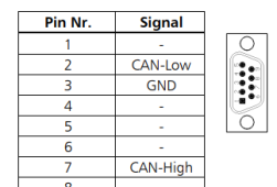
The only thing I can think of is that the CANBUS on the SMA SI requires the 120ohm resistor and pins 4/5/2 ... my IXXAT Usb-to-can does reference this is possible in the documents I have read but I don't have another setup on the side to test if this is true. I previously went through other pins for my electric motorcycle BMS / Controller to do the programming so I have never used those pins on my IXXAT before.

That said, the SMA SI will not run without a proper connection and input from the Batrium's Rj45 ... so it is "working" and at the same time not "working" ;) I haven't tried a new cable yet ... it seems odd that a cat8 cable wouldn't be "good enough or better" than a normal Cat5 cable for example.

So yeah, all that to say having your setup doing a can dump in a week is very helpful as you might run into the same problem I am with the pins or you might not. And theoretically I got your same setup it should "work" for me to see what is going on. But right now, I can't get anything but a connection ... no Rx or Tx data on the computer side of things.
 
@ChrisFullPower ... turns out my IXXAT device wasn't setup to read at pins 4/5 with the version I have ... I am now tracking traffic on the can network live while the SMA is plugged up after switching to the right pins on my db9 connector

1677849035699.png
Going to let it run a day then review the logs which should be "fun" since it is transmitting pretty fast.
 
Just realized the app I am using, IXXAT canAnalyzer mini, can log up to 1GB ... previously I thought it could only download the last 1MB of logs based on an export I did previously which lead me to start trying to listen for the SMA SI relay to reset so I could then pull the logs over a couple days.

Looking at the logs I do have I can see what the Batrium is sending and what the SI is sending which is good because I can cross reference relay events and errors sent from the SI with the Batrium logs all in one place when I do look at the logs tomorrow ... I say tomorrow as I just configured the app to drop logs into a fixed location on my HD and I am going to let it run a day before pulling them.

I am getting to learn about the SMA SI CAN protocol and encodings so I can read what is being passed as well as what ID's I should look at when I dive into the main log output tomorrow.
 
I am getting to learn about the SMA SI CAN protocol and encodings so I can read what is being passed as well as what ID's I should look at when I dive into the main log output tomorrow.
This may be of some help.....
 

Attachments

  • SMA Sunny Island CAN protocol.pdf
    491.8 KB · Views: 10
Had the relay trip while I was in the room so I pulled the short set of logs (as they are easier to manage) and looked at them.

Don't see any errors (35A) being thrown ... only active warning (which is always there) is that the temp sensor isn't connected on the SMA SI (why have that if you have a BMS with 5 of them :/ )

SoH (state of health) does go to 0 before relay is tripped ... not sure what that is a measure of and I am also not sure if that just happens when the relay is tripped (meaning the relay tripping causes the SoH to drop to 0 no matter what)

I included the logs pulled for this ... there is a lot of can traffic which I can't find documentation for. The 300-309 series I think is all SMA and the 351-356 is all Batrium to SMA ... rest of them are unknown and I haven't dived into decoding them yet.

Worth noting though, the SMA out CAN traffic is still sending signals when the relay is tripped which tells me it likely isn't a connection issue (aka wire issue, or termination of wire issue) or that probably wouldn't happen?

Ignore the 65535 value for battery current, that is more like -1 - -3, forgot to flip the endian value when making my notes.

photo_2023-03-09_07-13-18.jpg
 

Attachments

  • IXXAT_canAnalyser3_Mini_23-03-08_181828_a.zip
    43.8 KB · Views: 2
Attaching SMA SI settings, I can't see anything in here which would cause this behavior though but good to be thorough. Can do an examdif vs someone's system where this isn't happening maybe? idk.
 

Attachments

  • SI_Settings.zip
    3.6 KB · Views: 2
The errors thrown right after the relay shuts off are the Low Battery Modes (bat preservation modes) ... these settings look like they have default values. I looked at the firmware versions, Got (in this order #1 - #4) 7.302, 7.300, 1.004, 1.000 ... not sure what the current firmware version is as it is proving difficult to find on the SMA page.

EDIT: 7.304/7.300 is current
The SMA America site didn't like chrome for some reason, which is odd because Edge which is built off of chrome worked :/

SoH pg 110 in SI Manual
Only when the battery is new does its usable capacity correspond to the capacity specified by the battery manufacturer. As the battery ages and as a result of frequent insufficient charging, the battery's usable capacity may decrease considerably on a permanent or only temporary basis. The battery's state of health (display value "320.01 Soh") is a measurement of the present useable capacity expressed as a percentage relative to the nominal capacity. 100% means that the entire nominal capacity can be used. 50% means that only half of the original nominal battery capacity can be used. The state of health of the battery is determined using a self-adapting procedure which takes several charging cycles to collect accurate and reliable data. The current capacity for the Sunny Island is automatically adjusted downwards for temperatures below < 68°F (20°C) because of the significant drop in the usable capacity of the battery when temperatures fall below the rated temperature. For all lead-acid batteries, the nominal capacity is adjusted by a fixed factor of −0.6%/°F (−1%/°C). For NiCd batteries, a factor of − 0.4%/°F ( − 0.75%/°C) is used.
 
Last edited:
Extracted logs for a day or two, over 4 gigs of can traffic. Filtered for events where SoC was 0 then only included 300 series and 35A-F series ID's

Files found here https://docs.google.com/spreadsheets/d/196nEs3jqHcPWhH57wZDHS2x3UqB5Mm1gH-bnVlKV33k/edit?usp=sharing

Isolated 3 events and went forward / back in the records a bit to capture a couple 350+ series (from batrium to SMA) events
For full logs for this run you can DL it here https://drive.google.com/file/d/1hstDQPREjH7B5t0B_WLA3IsS5x5YQ_s6/view?usp=sharing

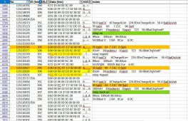
I modified the ID columns for colors, Green I believe comes from the SMA, Orange comes from Batrium to the SMA
 
Last edited:
Looking at these three events.
The highlighted 306 record, first two bits are SoH ... which comes from the SMA SI and read 0 SoH ... The description of this output in the manual says "State of health of the battery received from the external BMS"

This is where it gets odd .. if we look at 355 bit two the SoH is always 100% during these events. :/

BUT the key might be 305, bit set 4, which is SoC received from the external BMS ... which shows 0% before and during the event.

So this means the Batrium is putting out a signal, and the SI for whatever reason isn't getting it for the 1 second events ... ugh ... does this mean I need a RJ45 female to male with some pinouts I can tap into to see the signal reaches the end of the RJ45? I am tapped into the Batrium side of things right now as that is easier for sure >__<

Two thoughts.
1) The cable is somehow bad and somehow only shows this with random disconnects from BMS
2) The cable is fine an the jack is jacked ... somehow only showing this during random disconnects
3) (ok 3 thoughts), both the cable and the jack are fine and the SMA is screwed (somehow only showing this during random events :/ )

I can deal with 1 pretty easy and even test it pretty easily by setting up another cable, granted it wont be shielded

With number 2 though it is trickier to check and likely not too big of an issue IF I use my other SMA as the input for the batrium and then COM out to the current SMA COM in bypassing the port completely.

Not sure what I could do to check number three ... and the only thing I can hope is when the other SMA SI is master and the current one is slave the issue goes away.
 
Last edited:
It’s up and running! I haven’t had a chance to really sit down and test anything yet but I have noticed a few random dips where Batrium will send out a false reading over their UDP protocol and it will show up in my MQTT logger as a zero reading. I’ll see if I can get a screenshot or something tonight.
 
do you have eyes on the raw CAN traffic as well or just UDP at this time?
Good to hear your up and running!

Still noting patterns with the Batrium ... on day 5 of the battery being sub 100% after charging from 50% Soc and resetting the SoC daily after ~6Ah gets into the battery and the SoC reaches 102% and then resets to 100% ... so far I think 30Ah has been put into the battery after it did its bypass resetting of the SoC.
 
I have the CAN between the BMS and inverters up and running but I haven't got my PC on the bus yet. Maybe this week sometime?
 
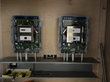
Main load shed relay tripped which is very odd ... Batrium not showing any critical events so I will have to pull the SI logs tomorrow. Not sure if I mentioned it but I have the relay for the load shed relay running off the SI battery +/- molex connector to avoid issues with relay 1 tripping all the time ... so it is kind of odd it would trip like it did and it makes me think this wasn't the first time.

Its almost like the SI rebooted or something because the AC power relay on the SI was also tripped and had to reset to the closed position ... Current voltage at the shunt (for my records later) 53.96, cell 3.34/3.37, SoC 100% [batrium values]
 
So I was right, the whole SI restarted ... it seems like it lost connection to the BMS, and historically this means the BMS was still transmitting but the SI wasn't getting it :/

Is there a coms card in this thing I can swap out? It seems like a much better test of equipment at this point.
 

Attachments

  • restart20230427.txt
    6.4 KB · Views: 1
New new new findings ... Since I had a chance to download the logs I am now comparing when my NAS stopped responding (meaning it shut off) vs the SI evt logs ... Every time the SI did the behavior above 0__0 ... ugh (https://diysolarforum.com/threads/sma-sunny-island-turning-off-nas.60821/ )

@ChrisFullPower have any issues with yours so far?

@Hedges ever hear about issues with coms being lost on these units when the coms were proven to be sent at the time they are lost?
 
The NAS disconnect issue I thought was AC dropout during grid switching. Did you find any logs indicating load-shed occurred? I remember some other thread where load-shed momentarily happened.

I haven't dug into SI comms much, and I see SMA Sunny Island CAN Protocol is for European model communications with BMS (different batteries supports vs. US model.)

I've used ComSync between multiple Sunny Islands and a Sunny Island Charger SIC40. That gets terminators both ends.

I've used RS485 adapter and ComSMA to put older Sunny Boy in offgrid condition for backup mode, and to connect Sunny Boy Control or Sunny WebBox. That also needs terminators at both ends, and what the documentation doesn't make clear is that pull up/down are also required somewhere. Sunny Boy Control and WebBox provide pull up/down, but without them connected pull up/down would be missing so data +/- sit at same voltage. Some of the Sunny Boy have headers which can be populated to connect the pull up/down resistors (in addition to a terminating resistor.)

On RS485 I've watched signals from Sunny Boy Control getting data from Sunny Boy. What I've never been able to trigger on and observe is the on/off grid signal from Sunny Island. Anybody know about that?

The need for Precharge resistor, which has been discussed elsewhere, is not mentioned in SI manual. But I see it in SMA Sunny Island CAN Protocol manual.

From reading this thread it appears a message from Batrium causes SI to believe state of health is zero, causing load shed. Usually I would be looking for poor signal integrity. Use a scope if you have one. Resistor termination (and pull-up if used), some wires disconnected, noisy ground (differential is supposed to help avoid), coupling to other wires (is comm wire next to power wires?)

If all other communication seems robust (and you wouldn't know without checking other data if it didn't cause visible behavior changes), then I' suspect the data coming from Batrium. Have you figured out what data goes into creating SoH figure? I see SI refers to some legacy algorithm for lead-acid; maybe that algorithm reacts badly to data from BMS.
 
Back
Top