diy solar

diy solar

Batrium SMA Sunny Island Integration issue?

The NAS disconnect issue I thought was AC dropout during grid switching. Did you find any logs indicating load-shed occurred? I remember some other thread where load-shed momentarily happened.
My SI load sheds like 6 times a day via relay1, which is why my actual load shed relay is no longer connected to it. Every time is because of BMS timeout. That said I monitored the traffic at those times and the BMS was transmitting, so far as I could tell since I could see SI and BMS traffic at the same time in the CAN logs, during an "event" ...

This time though the whole SI restarted ... it wasn't a load shed even but rater BMS lost contact event which triggered an autostart in the logs ... this has happened every time the NAS restarted according to my logs.


The need for Precharge resistor, which has been discussed elsewhere, is not mentioned in SI manual. But I see it in SMA Sunny Island CAN Protocol manual.
This is built into the BMS board, I verified it when I was in the process of adding one.

), some wires disconnected, noisy ground (differential is supposed to help avoid), coupling to other wires (is comm wire next to power wires?)
I have had the COMS in the load center passing AC at 90 degrees and DC in parallel at times. BUT as part of my experiment I have had it out of the load center completely and going straight into the face of the SI to avoid that issue. This cable is double shielded and has the ground wire connected on the BMS.


Have you figured out what data goes into creating SoH figure?
I think I found what this was in the past but I can't recall off the top of my head. All required COMS and some extra COMS options are created from the BMS looking at the raw CAN logs vs the CAN BUS SI documentation

The SI has terminators for COMs in two or three ports, forget which but they came that way second hand. This was previously used with AGM bank.
 
Shields block electrostatic coupling from voltage of other wires if grounded at one end (or both).
They only block coupling from currents if grounded at both ends.
DC of course can have sharp transient edges.

Locating cable far away for testing would eliminate most of that.
Currents flowing through ground, causing offset or coupling, would not be avoided by doing this.

What else ties the boxes together? If just conduit that also carries current (or regardless), you could check at least with DMM for AC or DC between boxes. Long shot; communication issues related to firmware is usually the most likely, if signal integrity is good.


We would like SoC and SoH figures to be reasonably low-pass filtered so they don't react to impossible instantaneous changes.
 
Shields block electrostatic coupling from voltage of other wires if grounded at one end (or both).
They only block coupling from currents if grounded at both ends.
Interesting, I didn't realize this but it 100% makes sense why this would be the case. I know I can semi-easily ground one end of this cable at the BMS ... the other end at the SI will be a little trickier ... will likely have to peal the cable back, expose the shielding, wrap and bond another wire to it, then bond that to the "grounding" pin.

Locating cable far away for testing would eliminate most of that.
Right now the cable comes straight out, at least 4" from power sources, from the load center and loops back up to the SI where it goes straight in through the face (which isn't attached) into the COMs port. At what distances I wonder do I need shielding and is having my BMS inside the load center a bad idea without shielding it.

What else ties the boxes together?
The SI and the Load center are bonded, nothing else physically attaching the two boxes. EDIT: Just looked at the boxes, it seems "ground" from AC1/AC2 are the only things boned, not the case of the SI or the "ground" at the battery terminal.

The LC is bonded to the transfer switch which is bonded to the Load panel which is bonded to neutral.

When I am using the SI as the primary grid manager AC2 is fed through the Load Panel (LP) from the Grid, and the SI provides power to the transfer switch loads.
When the SI is OFF the transfer switch is powered by their original circuits from the grid at the LP

you could check at least with DMM for AC or DC between boxes
I will double check this when I ground the cable. I believe before I hooked everything up I checked continuity between all sources and the bonded boxes and didn't find anything that shouldn't be bonded.


We would like SoC and SoH figures to be reasonably low-pass filtered so they don't react to impossible instantaneous changes.
I don't think there are any adjustments i can make at the BMS to change how this information is transfered to the SI ... I only know other people with SI's use this BMS.

Just updated firmware / software, it was only one version off ... I was excited a little as the change logs for the software (as it had an update as well) indicate ramp down targets now being available for "some" inverters ... don't think SMA was on that list because nothing changed with the ramp targets screen.
 
Interesting, I didn't realize this but it 100% makes sense why this would be the case. I know I can semi-easily ground one end of this cable at the BMS ... the other end at the SI will be a little trickier ... will likely have to peal the cable back, expose the shielding, wrap and bond another wire to it, then bond that to the "grounding" pin.

Ideal shielding is continuous around outside of connector. Pigtail works at lower frequencies, leaks at intermediate, is effective antenna when loop is 1/2 wavelength.

EM fields would couple differential mode into a wire separated at a distance from its return, or common mode into a twisted pair. Less than perfect symmetry in terminations and circuitry converts common mode to differential. Shielding reduces coupling into the wires. There are graphs showing attenuation vs. frequency for various types of twisting and shielding of Ethernet cable. Two layers of shielding provides further attenuation.

This approach is used extensively in systems which have to be hardened, and test labs inject interference, often with clamp transformers. The spec call out an upper limit on current which came from field tests with a wire fed into 50 ohm instruments. I disagree with that lab test limit because in practice shields do not have 50 ohm terminations. If field tests had used clamp current pickup rather than 50 ohm instrument, the measurements would have been different.

Interference happens, and error detection/correction improve results. We had a "Proflnet" system providing shutdown based on alarms and watchdog. It was routed in a lower grade Ethernet cable than specified for the length, parallel to power cables. During power line transients the shutdown tripped, even though no Ethernet errors occurred. Ethernet has more levels of software correction than Proflnet, which only used hardware layer of Ethernet. Replacement of cable with proper degree of shielding (except for allowed unshielded patch cords at end) eliminated the upset.

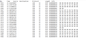
But since only certain messages are being lost in your case, I suspect firmware not interference.


Right now the cable comes straight out, at least 4" from power sources, from the load center and loops back up to the SI where it goes straight in through the face (which isn't attached) into the COMs port. At what distances I wonder do I need shielding and is having my BMS inside the load center a bad idea without shielding it.

Should be good enough if power is twisted. Separate power wires would project field to a distance.

The SI and the Load center are bonded, nothing else physically attaching the two boxes. EDIT: Just looked at the boxes, it seems "ground" from AC1/AC2 are the only things boned, not the case of the SI or the "ground" at the battery terminal.

I think SI and other chassis, including any boxes SI communicates with like a BMS or lithium battery which has metal chassis or ground terminal ought to be bonded together. But what you don't want is significant current in ground wires; that would induce common mode voltage in signals. And you don't want ground to be signal reference for a single-ended signal because then voltage offset in ground is seen as signal.

Any electrical circuit should be bonded to ground at just one place so no current flows in ground from another location. AC has neutral/ground bond usually at utility service entrance. Elsewhere, EMI filters have capacitors from line and neutral to ground. RF or switching noise currents do get coupled into ground. Filter capacitors are of a size such that 60 Hz causes about 0.1 mA to 2 mA or so to flow in ground, not a problem for most applications.

Ethernet RJ45 jacks have center-tapped transformers coupled to ground, and shielded cables connect to ground. The fact Ethernet signals reference ground at both ends might induce some common-mode, but balanced transformers reject most such interference. (A common design error in circuits and PCB is to connect PCB reference plane to Ethernet; it then radiates noise.)

RS485 is not transformer isolated. It has a "ground" or reference wire, and differential data lines. It rejects a certain amount of common mode, but only between positive and negative rails of the ICs. If boxes at both ends in a factory floor environment had reference bonded to noisy ground I would expect problems.

I think AC1 "ground", AC2 "ground" are connected together an to case. I think battery "ground" is connected to case. (AC1 "neutral" and AC2 "neutral" are connected together."

SMA doesn't require battery to be grounded but allows either positive or negative ground. I think NEC requires this voltage of battery to be grounded. I think running a battery wire of sufficient size from battery negative to SI battery "ground" is the way to clear a fuse on battery positive in the event of positive side shorting to case.

The LC is bonded to the transfer switch which is bonded to the Load panel which is bonded to neutral.

When I am using the SI as the primary grid manager AC2 is fed through the Load Panel (LP) from the Grid, and the SI provides power to the transfer switch loads.
When the SI is OFF the transfer switch is powered by their original circuits from the grid at the LP

This is why I would be inclined to route ground both ways, if that makes a loop so be it.

I will double check this when I ground the cable. I believe before I hooked everything up I checked continuity between all sources and the bonded boxes and didn't find anything that shouldn't be bonded.

You can check for DC resistance, and when powered check for AC and DC voltage. DMM probably on responds up to a couple kHz.

I don't think there are any adjustments i can make at the BMS to change how this information is transfered to the SI ... I only know other people with SI's use this BMS.

Maybe SI algorithm processes multiple parameters in such a way that when certain parameters are received it computes zero, then recomputes as more is received? Ideally SMA with a debugger would monitor state and when zero is seen, go back and determine how that happened. More difficult to do externally. On/off grid switching of "backup" was only one input signal and a couple parameters & functions affected, so I could readily determine what their bug was and SMA confirmed by reviewing firmware.

Just updated firmware / software, it was only one version off ... I was excited a little as the change logs for the software (as it had an update as well) indicate ramp down targets now being available for "some" inverters ... don't think SMA was on that list because nothing changed with the ramp targets screen.
 
Had the relay trip while I was in the room so I pulled the short set of logs (as they are easier to manage) and looked at them.

Don't see any errors (35A) being thrown ... only active warning (which is always there) is that the temp sensor isn't connected on the SMA SI (why have that if you have a BMS with 5 of them :/ )

SoH (state of health) does go to 0 before relay is tripped ... not sure what that is a measure of and I am also not sure if that just happens when the relay is tripped (meaning the relay tripping causes the SoH to drop to 0 no matter what)

I included the logs pulled for this ... there is a lot of can traffic which I can't find documentation for. The 300-309 series I think is all SMA and the 351-356 is all Batrium to SMA ... rest of them are unknown and I haven't dived into decoding them yet.

Worth noting though, the SMA out CAN traffic is still sending signals when the relay is tripped which tells me it likely isn't a connection issue (aka wire issue, or termination of wire issue) or that probably wouldn't happen?

Ignore the 65535 value for battery current, that is more like -1 - -3, forgot to flip the endian value when making my notes.

View attachment 138824
in your CAN dump, I noticed you received CAN identifier 0x10 & 0x70 for some time and then the identifiers changed to 0x305,306 etc. Can you please let me know what config changed to start receiving the expected CAN data (as per SMA data sheet)
 

Attachments

  • my_can_dump.png
    my_can_dump.png
    37.8 KB · Views: 7
Last edited:
in your CAN dump, I noticed you received CAN identifier 0x10 & 0x70 for some time and then the identifiers changed to 0x305,306 etc. Can you please let me know what config changed to start receiving the expected CAN data (as per SMA data sheet)
are you asking about the SI, the BMS, or the CAN READER ?
I think the BMS and SI output the traffic they are programmed for.

I didn't have to change settings on the CAN READER to see different parts of the traffic / signal ... it is mainly like a firehose of information. I filtered this out when I made other spreadsheets to illustrate the issues as I didn't think the 0x10 / 0x70 was part of the SI / BMS communications as it wasn't documented as such in the CAN Manual.
 
It’s up and running! I haven’t had a chance to really sit down and test anything yet but I have noticed a few random dips where Batrium will send out a false reading over their UDP protocol and it will show up in my MQTT logger as a zero reading. I’ll see if I can get a screenshot or something tonight.
Chris you ever get this hammered out?

I am still getting the unit cycling the relay as well as occasionally restarting ... thankfully, and ironically, I have important stuff on a external BMS now so when this happens I retain my internet connection for example.

Was trying to figure out what "third" device I need to COMM to the SMA SI since it has a lithium battery attached that wouldn't throw false readings and simply use the Batrium as a BMS monitor which controls a master relay.
 
UPDATE, and new issues:
So this system was decommissioned and setup in its new home as a slave unit to another master for my offgrid house build. I haven't had any restart issues I can recall since installing the BMS with the new unit, the master, receiving the signal.

BUT ... have some odd issues with the SI not listening to the BMS request for charging amps. The BMS will currently call for 20 amps, the SI will provide 20amps then quickly ramp up to 60+then back down to 20amps. During this time the BMS might cut off charging because cells are being over loaded with excess voltage. Then the process would repeat, the BMS calls for amps, the SI exceeds amps required, and the BMS cuts off charging. I believe this is limiting the amount I can charge my batteries in a day.

Hedges suggested the SI is dumping excess amps into the batteries and that might be the case but idk how to "fix" this problem. I have a SB setup with 12.5kW of PV and it has maxed out previously at 7.5kW AC in the past when I was observing it. The pattern I mentioned above typically happens after a larger load, like 1500-3000w, is placed on the system and the SI pulls from the batteries to facilitate the load request. When the load request is done the BMS's request for its 20 amps is met and exceeded.

excessAmps.png
excessAmps.png
 
How many amps is the BMS configured to accept? (that was the issue another forum member just solved; it was limiting charging because BMS set to 25A from factory. He increased that to hit desired charge rate.) Maybe BMS has to be set to allow your maximum load dump.

How large a battery?
SMA recommends various size batteries depending on Sunny Island system size. For split-phase (2x SI), they recommend 5x BYD LV Flex, which I think is 25kWh.


You're having problems with relatively small load dump, no more than 3kW.
I figure lithium always had to be kept below full, leaving headroom for load dump in AC coupled systems.
 
How many amps is the BMS configured to accept?
I can adjust it to do whatever amps I want it to. I had it at 112 if under 80%, then 40, then 35, now 20.
The BMS isn't cutting off because of the amps though it is because the cell voltage for one or more cells is too high. When it was set to 112 I would have 6 or so cells screaming at the BMS to shut the charging off vs the 1 now with it set to 20.

When I had it set to 35 the peak load from the SI was 70 amps when it ramped up at the start.

How large a battery?
Way undersized. 280Ah right now. We are looking to add 2 more that size though as I don't think the single one will be enough for when we want to live here. Had one day the battery got down to 24% with our "normal" construction loads after a couple days of clouds / rain / snow etc.

SMA recommends various size batteries depending on Sunny Island system size.
I thought the sizing was based on the KW at the array? So a ~13kW array would at minimal need 1300Ah of battery which would be 5 of my 280ah batteries if I recall correctly.

I will read through this really quick. Thanks
 
from that document "AXITEC AXIstorage Li 8S QTY 3 or more for offgrid with splitphase" That is ~22kW of storage. 3 of my 280 batteries is ~32kW of storage.
 
SI manual recommends battery size as a function of AC coupled PV (with AGM I have 1/3 what they recommend.)
The lithium compatibility list, they go by number of SI, looks like less than the per kW PV recommendation.

More Ah would mean voltage doesn't run as far. Maybe compatible batteries are configured to keep voltage low enough for some headroom, but I don't know.

If BMS max current is set low, it would disconnect or maybe tell SI to shut down.
If BMS current set higher, maybe it accepts the current while asking for less, unless cell voltage shoots too high.

Can you tell BMS to request lower charge (bulk/absorb) voltage? Then SI ought to taper off, except for brief load dump.
 
This is what I can adjust. The 20 setting at Current is what I have been changing, at the old place when this was setup as a battery backup system I had the Current set to 112 but it rarely got triggered as we kept above 85% most of the time. This BMS is not "great" for eve cells but it has a pretty setup so I am rolling with it right now.

1703183946749.png
 
Hi Burton, it's been a few weeks since your last post, and I'm wondering whether you've resolved the communications issue from Batrium BMS to Sunny Island master inverter. Do I understand correctly this may have gotten resolved by the re-installation, and that that involved substituting a different SI master inverter? Is your current thinking that the "load dump" overshoot of certain cells is because your battery is simply too small? Or do you think some of your cells are actually too high internal resistance, i.e., they may be "marginal" or "bad" cells?
The reason I ask is because I'm considering Batrium as the BMS for my under-construction LTO battery system, which will be ~1000 AHr @ 48V, feeding four Sunny Islands in "2Phase4" configuration.
I'm comparing the REC master-slave system (three boxes required for my system) vs the Batrium (WatchMon CORE plus 2 K9 LTO CellMate boxes).
So both system would require a total of 3 modules (1 + 2), but the REC prices out considerably higher. Just looking for other folks' experiences with either Batrium or REC BMS and SMA Sunny Island (I've already read all relevant threads on this forum, as far as I can find).
 
Last edited:
I have not resolved the issues :/

I can't use any of the logic on the SI's to trip events right now because of the untrustworthy coms.

The coms has dropped in the last month about 4 times causing a complete restart of the systems while I was there, it is at the point I am considering getting a different bms ... I did however post on a thread on batrium's forum where someone had a similar issue with victron but had no reply yet. https://community.batrium.com/t/com...-and-victron-cerbo-gx-drops-in-and-out/408/12

The spiky cells are less frequent with setting the amps down a bit and I am still able to charge the batter up to say 85 from 25 on a very sunny day after a couple cloudy days.

I have a second battery I am going to building this next month which should allow me to bump the amps up but it to will be connected to a K9 which is going to the batrium ...

Right now I cannot recommend the batrium to a SMA user using LFP cells, it isn't made for them and likely don't balance them as well as a victron unit would for example. It is frustrating for sure as I don't want to have to get more equipment.
 
UPDATE:
NOT HAPPY .... NOT HAPPY AT ALL.


Power went out at the property we are building out while I was at our other home and when I went in later that evening it took me a good 2 hours to get it back online. The cause, the Batrium BMS reverted to a factory state ... no clue why ... and the only reason I know is when I went to recommission the system, as it had somehow lost all its settings, my password provided with the unit did not work but the factory default password did work.

I am seriously now looking at dropping my batrium and installing something else ... I cannot have this product fail when I am not around and have my family be at risk because I can't walk them through the process to restore the BMS.

It is bad enough that I can't use the SI relays because the BMS can't seem to communicate properly with the SMA SI's without occasionally timing out or reporting a sell is over or under the right SOC but to completely reset itself is unacceptable :/

I have not opened a ticket with batrium yet, but given it has been a while since I posted I was having issues with my unit and SMA similar to the issue with the previously "fixed" victron units I am not expecting much.

@ChrisFullPower how has your build working out?
 
I've had that happen with software/firmware updates and there was a software/firmware update in the last few weeks. I don't know if there is a setting for automatically updating, I choose when I do mine. There is a backup file on your laptop used for the toolkit, it will revert your settings to what you had. I updated 2 laptops as I run Toolkit on both and one had trouble with the install when reopening the Toolkit such as the password problem you had. I can't recall how I did get it to work, the laptop with the problem was the one in the shop and I did take it to the house system and plugged in the RJ cable, then installing the backup file if memory serves me correctly.

If you have internet access you can now use web integration and that might help in your situation. I assume the settings and data will be stored in the cloud and you can access it anywhere with internet access. Unless you are already using it?
 
I've had that happen with software/firmware updates and there was a software/firmware update in the last few weeks. I don't know if there is a setting for automatically updating, I choose when I do mine.
I have not had this device hooked up to any computer or the web for months ... it was "working," with previously mentioned issues, for that long in my new offgrid setup :/
 
There is a backup file on your laptop used for the toolkit, it will revert your settings to what you had.
Just tried this .... I suspect i did some settings by my charging was defaulted ... and when I select ramped all options are zeroed out >__<
 
I have not had this device hooked up to any computer or the web for months ... it was "working," with previously mentioned issues, for that long in my new offgrid setup :/
Then it wouldn't be the update that caused it. I do recall one time I did the update and did not know how to use the backup file (still have a hard time with using the backup file and remembering how to do it) and it reverted to factory default settings. That caused the breaker to trip as I run custom settings. That sucked big time, I feel for you. It took some time to get settings back to where I thought it should be set.

A wonderful product if the documentation was better, support wasn't a paid service for simple questions, and interaction/integration with other components doesn't work well. I love the toolkit and cell graphing.

I went JK on the shop system, didn't need inverter comm so have the older proven model. I'll still run the Batrium in the house for that bank, if the CORE died tomorrow I'd have to think long and hard about replacing it. If a K9 dies, I'll probably just install a JK instead.
 
Back
Top