JoelE
New Member
I've done my best to make this install as cheap and easy for myself as possible, while still attempting to meet all the NEC 2020 code requirements as far as I've read them.
I wanted to solicit your feedback on my current design (note: there should be a junction box between array and disconnect for the roof penetration pass through of DC).

On the roof:

Outside (under patio):
Few things to note:
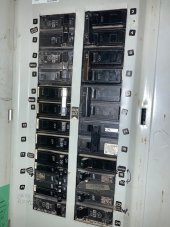
1. I have a split bus main service panel, and I'm relying on the exception in NEC 2020 that allows for this. No plans to upgrade the MSP.
2. I have an existing 50a branch originally permitted for a hot tub install, which I plan to derate to 40a for my inverter which has a max output of 32a. The hot tub is decommissioned but the sub-panel is in a perfect spot for me to mount my inverter near and backfeed into. The 40a backfeed breaker will sit on the 100a busbar, protected by a 70a breaker on the main (200a) busbar. [(70 + 40) = 110a. 110 < (100*1.2)]
Questions:
1. Any reason I can't use this particular MC and run it all the way from soladeck to the DC disconnect, and can you recommend a conduit connector for it for attaching to the soladeck?
2. For the PV wire MC4 connections at the strings, can I run the cable with MC4 connector on one side, and directly into the soladeck on the other side? For example, if I buy an 1 extension cable of sufficient length with MC4 already crimped on each side, can I cut it in half and save myself the need to buy a crimping tool or any MC4 connectors? So I'd have on string one the negative side running back to the jbox. On string 2, I'd have the positive side running back to the jbox?
3. If you think my plan to use the split bus panel is not to code, can you please give a reference supporting that? Or if you think I should do a supply side tap instead, keep in mind I'm getting this hybrid inverter with a plan to expand into a battery system in the future. And I prefer to not have to shut down all the power to my home and make things more complicated for myself unless I have to.
I wanted to solicit your feedback on my current design (note: there should be a junction box between array and disconnect for the roof penetration pass through of DC).
On the roof:
- 2 strings of 11 panels each - Canadian Solar BiHiKu CS3W-445MB-AG 445W - 10AWG PV wire connecting the 2 strings to the Soladeck
- Tigo TS4-A-F at each panel for RSD
- Unirac Solarmount system with Flashloc attachments (so I don't have to mess with getting under shingles at all except for the junction box)
- Soladeck or EZ Solar XL junction box to pass through the 2 strings through the roof
- 10/4 w/ ground Metal Clad cable, runs from roof junction box all the way to outside under the patio - Red and black will be used for string 1 and 2 hot side.
Outside (under patio):
- 10/4 w ground MC runs down from attic to DC disconnect switch
- 10/4 w ground MC to Growatt MIN 7600 TL-XH-US Inverter, connecting both strings
- Inverter to AC Disconnect with 8 AWG copper in conduit.
- AC Disconnect to existing sub-panel with 8AWG copper in conduit
- Existing Sub-panel runs to Service Panel with 6AWG copper
- 6x6 placard at the Meter with a sitemap to the location of the disconnect. Meter is approx 10ft from the disconnect switch.
Few things to note:
1. I have a split bus main service panel, and I'm relying on the exception in NEC 2020 that allows for this. No plans to upgrade the MSP.
2. I have an existing 50a branch originally permitted for a hot tub install, which I plan to derate to 40a for my inverter which has a max output of 32a. The hot tub is decommissioned but the sub-panel is in a perfect spot for me to mount my inverter near and backfeed into. The 40a backfeed breaker will sit on the 100a busbar, protected by a 70a breaker on the main (200a) busbar. [(70 + 40) = 110a. 110 < (100*1.2)]
Questions:
1. Any reason I can't use this particular MC and run it all the way from soladeck to the DC disconnect, and can you recommend a conduit connector for it for attaching to the soladeck?
2. For the PV wire MC4 connections at the strings, can I run the cable with MC4 connector on one side, and directly into the soladeck on the other side? For example, if I buy an 1 extension cable of sufficient length with MC4 already crimped on each side, can I cut it in half and save myself the need to buy a crimping tool or any MC4 connectors? So I'd have on string one the negative side running back to the jbox. On string 2, I'd have the positive side running back to the jbox?
3. If you think my plan to use the split bus panel is not to code, can you please give a reference supporting that? Or if you think I should do a supply side tap instead, keep in mind I'm getting this hybrid inverter with a plan to expand into a battery system in the future. And I prefer to not have to shut down all the power to my home and make things more complicated for myself unless I have to.