diy solar

diy solar

Combiner Box Help

OffGridBC

New Member
Joined
Apr 25, 2024
Messages
8
Location
BC
Hi, we recently realized our combiner box is not correct and we need an upgrade but before I buy a new one I want to make sure what I am getting is correct this time. Thank you in advance for your help.

Equipment I have:
- 16 - 450W panels wired in strings of 2 then parallel in two separate groups of 8 panels total. Would that be two sets of 2s4p?
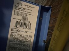
- panels connect to 2 MPPT controllers (each group of 8 panels connects to a controller). Controller specs are 155Vdc and 100 amps each.
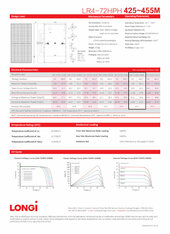
- Panel specs - 49.3 Voc/V and 11.60 Isc/A
- 48V system
- Temperatures here can range from -30 C in winter to + 40 C in summer

My questions are:

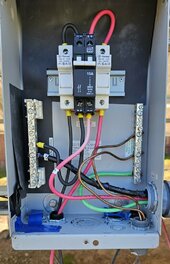
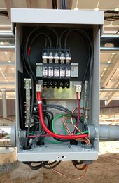
- My understanding is when you combine 3 or more strings, each string must have its own fuse or circuit breaker and then the combined output will also need a larger circuit breaker. Since we have 4 strings in each set of 8 panels, there would be 2 sets of 4 fuses or breakers, with each set then combined into one large breaker?

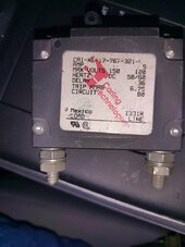
- Each string fuse/breaker would be 11.60 Isc x 1.5 = 17.4 amps bumped up to 20A (which matches the panel "fuse series rating" of 20A). Each set of four 20A breakers would then be combined into one larger output breaker of 80A. Is this correct?

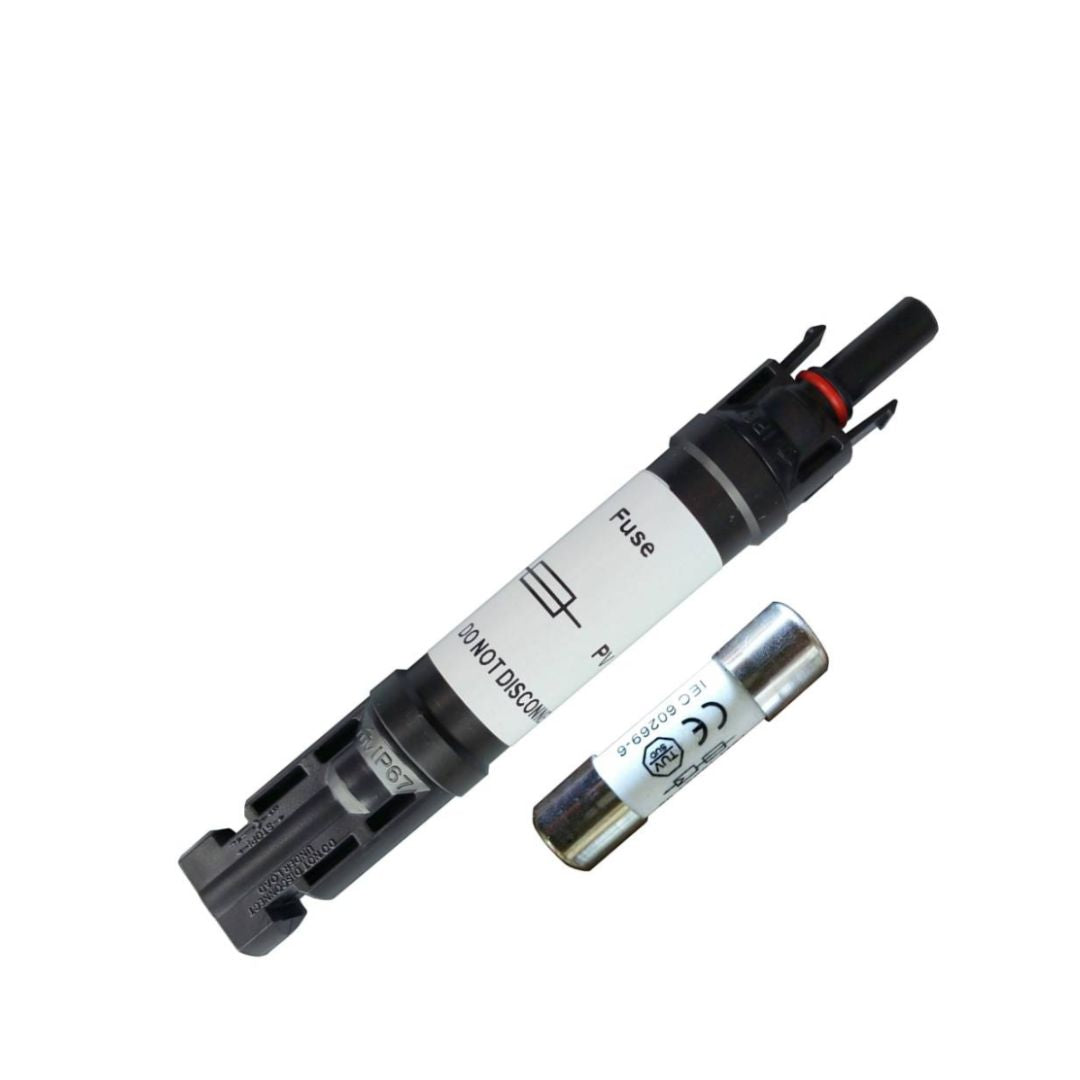
- Is it better to use fuses or breakers for each string, or doesn't matter?

- I read in another post that the fuse/breaker size is for the wire size not the load, so not sure if my calculations above are correct or if I need to go off the wire size instead?

- I am having difficulty finding a combiner box that fits the amps and breaker sizes I need. I found this one on Watts247 (https://watts247.com/product/solar-panel-combiner-box-4-circuits-to-2/) but the fuse size is 15A instead of 20A. Or could get a Midnite MNPV12 Combiner Box and piece it together with the correct breakers and surge protector. Or if anyone can recommend a suitable box that would be greatly appreciated.

Thank you!
 
Why do you only have 2 panels per string? That's how our electrician hooked them up. Should we have 3 per string? I don't quite understand the advantage/disadvantage of having 2 vs 3 per string.

That’s only about 100vdc per string? Yes, according to the solar panel specs

Is maximum input for your controller 155vdc? It says solar input of 18-155 Vdc

What is controller manufacturer and model? AIMS Power model Scc100AMPPT

What is the voltage of the battery bank are you charging? 48V

How many AH is the bank? 890 Ah I believe. We currently have 16 flooded lead acid batteries. They are 6V each connected in groups of 8 batteries, then connected together. Each set is connected to a controller. Battery specs say 445 Ah / 20Hr. We are looking into switching out the lead acid batteries for lithium.

Thank you for your reply! I answered your questions above and attached pictures of the specs for the panels, controllers, and batteries. Living off-grid with solar is new to me and I have been trying to learn but still don't understand it all so I appreciate the help/advice.
 

Attachments

  • solar panel specs.jpg
    solar panel specs.jpg
    169.6 KB · Views: 9
  • controller specs.jpg
    controller specs.jpg
    177.8 KB · Views: 9
  • battery specs.jpg
    battery specs.jpg
    211 KB · Views: 9
Thank you for your reply! I answered your questions above and attached pictures of the specs for the panels, controllers, and batteries. Living off-grid with solar is new to me and I have been trying to learn but still don't understand it all so I appreciate the help/advice.
You have lead acid batteries which is substantially different than LIFEPO4.
I will have to wait on someone who knows how to charge, equalize and maintain PB to help you with that aspect.

It looks like you only have 1 input to that CC.

Do you have more than 1 of the Charge controllers?

Are you planning on running

2 panel strings x 4 in parallel to 1 charge controller and 2 panel strings x 4 in parallel to another charge controller?
2s4p and 2s4p.

In other words are you using 2 of those aims charge controllers or just 1?


Yes you would have to fuse each parallel string.

They make MC4 in-line fuses for parallel if you want to use that rather than trying to find a combiner box that works.

 
Last edited:
You have lead acid batteries which is substantially different than LIFEPO4.
I will have to wait on someone who knows how to charge, equalize and maintain PB to help you with that aspect.

It looks like you only have 1 input to that CC.

Do you have more than 1 of the Charge controllers?

Are you planning on running

2 panel strings x 4 in parallel to 1 charge controller and 2 panel strings x 4 in parallel to another charge controller?
2s4p and 2s4p.

In other words are you using 2 of those aims charge controllers or just 1?


Yes you would have to fuse each parallel string.

They make MC4 in-line fuses for parallel if you want to use that rather than trying to find a combiner box that works.

Thanks again for your reply! We have 2 charge controllers. They are hooked up exactly like you said - 2s4p and 2s4p. Sorry I thought I mentioned that in my original post. Someone told us they are usually connected in strings of 3 but because we have 8 panels to each controller we did strings of 2 (otherwise would be one string of 3, another string of 3, and a string of 2 connected in parallel). Is 2s4p okay or is the latter better?

Thank you for sharing the MC4 fuses - I didn't know about those. So basically they go where the solar panels connect together rather than fuses in a combiner box. That might be a better way for us to go. Right now each 2s4p group of panels is connected to one larger breaker, which is connected to a charge controller. Our breakers kept tripping. That's when I learned we need to have fuses or breakers for each string. I just wasn't sure if my math was correct and how the panels were connected was correct. A few questions if we use the MC4 fuses instead...

- Do we use the MC4 fuses where each two panels are connected in a string? Or where they are connected in parallel to the next string? There are connections to both so just want to confirm where we replace the other connections with MC4s.

- Panel specs say 11.60 Isc and "fuse series rating" of 20A - is that the fuse size we need? Someone else told me we wouldn't need over 15A but we don't want the fuses or breakers to keep tripping so I want to make sure to get the right size. I saw in another post someone said the Isc amps should be multiplied by 1.5 to allow for surges and such. So 11.60 x 1.5 = 17.4 amps bumped up to 20A (which matches the panel "fuse series rating" of 20A).

- If we use the MC4s instead of fuses in a combiner box, then I assume we can keep our current combiner box that has 2 bigger breakers where the two sets of 2s4p come into? If each string of panels is 20A fuses, would we need each breaker to be 80A then?

- If we go with a combiner box rather than MC4s, is there an advantage to using fuses over breakers for each string? Originally we thought if we could get a combiner box with breakers for each string then if one tripped it would be easier to just flip the breaker back on rather than replacing a fuse. Also, it would be easier to see which string is out because the breaker is more visible rather than having to open each fuse box to find the blown fuse. But I see more about fuses so just wondering if there is a benefit of using one over the other?

Thanks again
 
This is how I wire a single string PV array in the combiner box, but it applies to multiple parallel strings as well. In this case, one string for up to 500 VDC.

The PV + and PV- each enter into a DIN rail mounted solar fuse holder. In this case, 20 amps. Then they exit the fuse holders and go into a double pole breaker, rated for 600 VDC and 15 amps. They exit the breaker as follows: The PV+ directed to a DC disconnect switch, one switch pole for every PV+. The PV- exits the breaker to a PV- buss bar. The lightening arrestor (Midnite Solar 600 VDC rated) is attached to the ground buss bar in the combiner box, the PV- buss bar and the PV+ wire before the PV+ is attached to the solar fuse. Leaving the combiner box is a wire from the PV- buss bar, the ground buss bar and the PV+ wire (goes to disconnect switch), then they can go to the inverter. The ground buss bar is connected to the array by bare copper wire bonded to all metal parts of the array, the rails and panels. There is also a ground earth rod too, but this is controversial on this site.

This provides protection to the inverter on the PV+ and PV- sides and 2 points of disconnecting power to the inverter, at the breaker PV+ and PV- and the switch PV+.

If doing parallel array strings, the photo of combiner box one shows lower voltage strings in this case and only the PV+ travels across a single pole breaker. The PV+ line was fused with a solar breaker using a fusible DC disconnect switch. The bottom of the breakers uses a buss bar to connect the PV+ to a single point of exit to the disconnect switch. This method is cheaper, but does not protect the PV- side of the circuit to the charge controller. The PV- does carry current too.
 

Attachments

  • 20240319_113229.jpg
    20240319_113229.jpg
    149.9 KB · Views: 23
  • combiner box-1.jpg
    combiner box-1.jpg
    138 KB · Views: 24
Sorry busy this weekend.

Honestly if it were me, I would get a higher voltage Charge controller and avoid all the parallel inputs.

It just makes it so much easier.

Reconfigure your array to match and be done with it.
8s2p


I realize not everyone can go buy one but your cost in wiring, breakers and combiners would cost as much or more than the Charge controller anyway.

Hope this helps..
Thank you. I think that is likely what we will do.
 
Your on a 48 volt system right?

Looks like you'll need a 500v controller with potential for 125 amps of charging at 48 volts.

The EG4 one would be slightly over paneled with the 100amp charge output. Shouldn't be the end of the world in the PNW as our sun sucks anyways.

There is a Schneider mppt in the lower mainland for sale, but it only has an 80 amp output so you'll definitely scrub the power at peak sun.

It will really tidy things up to go 8s2p.
 
This is how I wire a single string PV array in the combiner box, but it applies to multiple parallel strings as well. In this case, one string for up to 500 VDC.

The PV + and PV- each enter into a DIN rail mounted solar fuse holder. In this case, 20 amps. Then they exit the fuse holders and go into a double pole breaker, rated for 600 VDC and 15 amps. They exit the breaker as follows: The PV+ directed to a DC disconnect switch, one switch pole for every PV+. The PV- exits the breaker to a PV- buss bar. The lightening arrestor (Midnite Solar 600 VDC rated) is attached to the ground buss bar in the combiner box, the PV- buss bar and the PV+ wire before the PV+ is attached to the solar fuse. Leaving the combiner box is a wire from the PV- buss bar, the ground buss bar and the PV+ wire (goes to disconnect switch), then they can go to the inverter. The ground buss bar is connected to the array by bare copper wire bonded to all metal parts of the array, the rails and panels. There is also a ground earth rod too, but this is controversial on this site.

This provides protection to the inverter on the PV+ and PV- sides and 2 points of disconnecting power to the inverter, at the breaker PV+ and PV- and the switch PV+.

If doing parallel array strings, the photo of combiner box one shows lower voltage strings in this case and only the PV+ travels across a single pole breaker. The PV+ line was fused with a solar breaker using a fusible DC disconnect switch. The bottom of the breakers uses a buss bar to connect the PV+ to a single point of exit to the disconnect switch. This method is cheaper, but does not protect the PV- side of the circuit to the charge controller. The PV- does carry current too.
@glandpuck I have a concern about your second image, combiner-box-1.

I am assuming that you have the MNPV6 combiner box.

I am assuming that the breakers are the polarized MNEPV breakers.

I see that you have the + lines from the strings connected to the top side of the breakers, and the combining metal busbar joining at the bottom or + side of the breakers.

If these are indeed the polarized MNEPV breakers, I think this may be backwards. The '+' side of the breakers should face the side with the higher potential, which before the SCC is the panels, as such, the strings should connect to the + side of the breakers, and the combining bus bar should be at the top.

Take a look at this image from midnite solar showing the busbar at the top:


Of course I may misunderstand something, but these are my thoughts given what I see.
 
The breakers are bi-directional.
Ok, if these are the newer non-polarized MNEPV breakers, this will work, but as your setup is not the convention, I do not want the OP or anyone else to be misled.

If you are using polarized breakers, the + side of the breaker should always be toward the side of higher potential. In this case, that is the panels. I have kept this convention where appropriate even with non-polarized breakers for clarity.
 
Thanks @Brucey. For the record, the MNEDC panel mount non-polarized breakers that I use have Line and Load markings. The Line side goes to the higher potential.
 
Thanks @Brucey. For the record, the MNEDC panel mount non-polarized breakers that I use have Line and Load markings. The Line side goes to the higher potential side.
Interesting, must vary by model and date of manufacturing perhaps. My mnedc250s and mnedc60s aren't marked
 
Here is my spare MNEDC 5. Note the Line/Load is marked on the sticker, not etched in the plastic. So the sticker may be specific to the lot. MNEDC breakers are rebranded Carlings:
 

Attachments

  • IMG_20240430_205744.jpg
    IMG_20240430_205744.jpg
    103.3 KB · Views: 5
Here is my spare MNEDC 5. Note the Line/Load is marked on the sticker, not etched in the plastic. So the sticker may be specific to the lot. MNEDC breakers are rebranded Carlings:
Crap I need to look at mine then.
Don’t remember seeing that.
 
Ok, if these are the newer non-polarized MNEPV breakers, this will work, but as your setup is not the convention, I do not want the OP or anyone else to be misled.

If you are using polarized breakers, the + side of the breaker should always be toward the side of higher potential. In this case, that is the panels. I have kept this convention where appropriate even with non-polarized breakers for clarity.
Hmm. I would say you do what works for you. Look at the photo of my Double Pole polarized breaker. There is both a -- and a ++ on the top and bottom. So your convention would result in a null situation with no clear answer for the installer since the ++ would be on the bottom too. But what is the "potential" across the the PV--? Isn't it the same as across the PV++, just in a different direction?

If anyone has any doubts about how to install a Midnite Solar polarized breaker, then contact Midnite Tech support, they get on the phone and are very helpful.

If you look earlier in the thread at my photo posted on the left using the double pole breaker, you will see what I believe is the proper best practice for wiring a fused and breaker polarized combiner box for today's higher voltage world. The photo on the left was wired in 2016 for a low voltage ( less than 150 volts) parallel string combiner box to a stand alone MPPT charge controller.
 
Back
Top