Cheap 4-life
My body is 2.63 trillion volts, .07v per cell
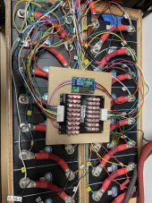
It appears that your cells have spacers to keep them separated so that any expansion would not put pressure on the terminals or loosen your nuts. so your cells are not compressed to each other enough for the swelling to matter. That’s kinda what Offgridgarage is doing but he has no compression. Just mats between the cells.
Seems you are using hard spacers in the corners where the cell doesn’t swell. Compress at these spacers and use soft mats in the middle between the cells. This would stop movement at the busbars when the cells swell. What did you use in the space between the cells.
But are these cells actually compressed in your configuration? Doesn’t seem so with the large gap between each cell.
Edit: the insulators between the cells are also hard so there is compression throughout the entire side of the cell.
Last edited: