Markus_EG4
I am from Germany. Don't mean to come off rude
The CTs need to face the inverter. You just cant get L1 CT and L2 CT mixed up. If you do it will read wrong. Not a big deal its a easy fix with settings.
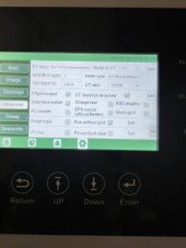
Yes Rhino it is solved. in my case it seems was a two fold issue. The firmware makes a major change to how the option of self consume works. it does now what it is supposed to that is first solar/Battery then grid last. no more import and export period. only import when the solar is gone and batteries are dead or hit the SOC cutoff. as for the second error, they tell me the CT's were backwards, in a way that I do not understand. As mine face the inverter on the AC line between grid feed and inverter AC input connection as per the manual. This is of course opposite most other inverters on the market that use CT's to measure the current going back to the grid. but when I question Marcus he said that the were reversed on the L1 and L2, indication that somehow there is a difference between the two CT's. I have to admit that makes no sense to me but I looked at inverter and the reverse install check box is selected which tells me the direction of the CT's is like the rest of the world and should point to the grid connection not the inverters and the manual is wrong.Thank you. Like @timselectric I do not currently have one but have been talking to James about getting one. I like to fully understand the system/support/issues before getting one which is why I've been asking questions and commenting.
Would also like to see that this updated firmware version fixes it for @rmacgurn.

So, is this attachment correct placement of CT's?Here is the diagram.
Yes I have 8 in R&D that way.So, is this attachment correct placement of CT's?
Reversed as in you may have had CT1 on red and CT2 on black. Note Black and Red aren't always the same in every community. I hear Houston is backwards.this is the typical install for CT's in solarc or solaris etc,,note it is reversed to your diagram. that is why I think you needed to do the check box to reverse the CT direction on the inverter as we have check the direction several times for past tech and flow it was installed per your diagram.
View attachment 156102
here in Costa Rica from the meter is 3/0 all three black. we don't have colors in large sizes but sometimes white only otherwise all 2/0 up is black so I have no clue which is L1 or L2. but I think the reverse feature was for arrow direction now L1/L2 this is new to me.Reversed as in you may have had CT1 on red and CT2 on black. Note Black and Red aren't always the same in every community. I hear Houston is backwards.
Yes for CT the L1, L2 and direction matters.here in Costa Rica from the meter is 3/0 all three black. we don't have colors in large sizes but sometimes white only otherwise all 2/0 up is black so I have no clue which is L1 or L2. but I think the reverse feature was for arrow direction now L1/L2 this is new to me.
ok explain why that would make any difference in calculating the power feed back into the grid. its the total so both legs so if the CT for L1 is on L2 and vs version the totals are still the same unless the inverter is doing some kind of phase shifting algorithm or something odd. I understand why having the arrows going the wrong way would make a big difference as it would flip the sign on the flow of current. but not why there is a specific CT for each leg.Reversed as in you may have had CT1 on red and CT2 on black. Note Black and Red aren't always the same in every community. I hear Houston is backwards.
yeah that is my option also.Swapping the CTs between L1 and L2 should make no difference whatsoever.
Because L1 and L2 are 180 Degrees out of phase from each other. The inverter has grid sensing feature so whats tied to L1 needs L1 CT whats tied to L2 needs L2 CTyeah that is my option also.
I have 14 CTs in my panel. I'm looking for supporting data that explains it better.ok explain why that would make any difference in calculating the power feed back into the grid. its the total so both legs so if the CT for L1 is on L2 and vs version the totals are still the same unless the inverter is doing some kind of phase shifting algorithm or something odd. I understand why having the arrows going the wrong way would make a big difference as it would flip the sign on the flow of current. but not why there is a specific CT for each leg.
Well, we usually think of L1 as the line coming in from the grid on the left side of the meter. I think what Markus is saying is that they define L1 not as how it comes in, but how it connects to the inverter.I would say if some one does not know which is which in the main panel, with all power off they could add the neutral to one leg testing it with a ohms meter for continuity. that would tell you if you have them on l1 or l2.
I don't own one but I am still considering one. The feedback for the grid is a big concern for me.Here is the diagram.


