jwrezz
New Member
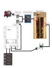
I have a generator interlock on the side of my house. L14-30. I use a gasoline predator inverter generator with it, but I don't have the need too often. Was wondering if as a start if I could get some batteries, and I already have one and access to a second whistler 3kw modified sinewave inverters. Could I attach batteries to inverters and use a y adapter with dual 120v plugs to LM14-30 like this:
y-adapter
Then just flip my generator interlock and it'd work? Of course I'd love to gradually expand the system with LiFePO4 racks, and real inverters, but would this work?
y-adapter
Then just flip my generator interlock and it'd work? Of course I'd love to gradually expand the system with LiFePO4 racks, and real inverters, but would this work?