diy solar

diy solar

Grid and Off-Grid Neutrals bonded to same ground ?

meetyg

Solar Addict
Joined
Jun 4, 2021
Messages
1,140
Hi.
I'm thinking about changing my current grid-tied system to a Hybrid All-in-one for backup purposes. I have 230v (European) single phase AC.

My question is this: Would it be OK to bond the inverter's output Neutral to the same ground as my grid's ground (which is also bonded to the grid Neutral) ?

The inverter I'm planning on getting is a MUST PH1800 Plus Hybrid, with Grid-tie, AC bypass and UPS modes (similar to many MPP Solar LVX models).

From the instruction manual I was able to get online there is no mention about bonding. Maybe the inverter takes care of all this and I don't need to do any bonding on the output?

Thanks.
 
Last edited:
I understand all grounds within a building are to be bonded together.
Neutrals are supposed to be bonded to ground.
So I think the answer is "Yes".

However, if you have an inverter that is also fed from the grid, and doesn't have a neutral so you're using an auto-transformer to create split-phase, we've seen it documented may ways that are wrong and unsafe. It ought to be UL listed and connected according to instructions.

There may be ways to make it safe with isolation transformers. Some manufacturers have a neutral switching scheme which appears good.

But if you're using a 230V (Line, Neutral) inverter as originally intended, with Neutral grounded (not treating output as L1 and L2), that seems OK.
 
Yeah, It's only for 230v single phase.
I'm planning on running it this way:
1. Solar will go to power loads and charge the battery.
2. Grid will be connected for bypass when loads are above Solar input.
3. Battery will be used mainly as backup if grid fails. I guess I will cycle the battery lightly once in a while.
4. Any Solar excess will go to the grid.

I think I'll simply have to tinker with the inverter when I get it, checking to see when/if it bonds Neutral to Ground.

But I wanted to make sure that I can do an external bond on the output, just in case it doesn't already do this.
 
Yeah, It's only for 230v single phase.
...
2. Grid will be connected for bypass when loads are above Solar input.

This what I'm unclear about.
Do you have 120/240V (or 115/230V, same thing) split-phase, typical power to U.S. homes?

That is L1 = 120Vrms, N = zero (grounded), L2 = 120vrms
L1 and L2 are out of phase so there is 240V between them.

Inverter has L = 230V, N = zero

So is the idea that when inverter powers load off battery, load sees 230V and (possibly grounded) neutral. When grid powers load, load sees two 120V phases for 240V?

That could work, if inverter switches both poles (probably does.) If inverter grounds its "N" only when disconnected from grid, then load gets 230V split-phase like in Europe. If it doesn't bond neutral to ground then the load is floating, may be OK but of course make sure it has 3-wire cord with chassis ground. I know there are several schemes in Europe involving where neutral gets grounded. Not necessarily "correct" or to code for U.S. but functional.

I assume you'll have a breaker panel downstream of the inverter, not using its neutral busbar (just ground), and all 2-pole breakers. (Don't want "neutral" to ever be hot, and single pole breaker isn't rated for 240V)
 
Depending on where in your system you connect to ground, you may permanently trip GFCI outlets.
 
This what I'm unclear about.
Do you have 120/240V (or 115/230V, same thing) split-phase, typical power to U.S. homes?

That is L1 = 120Vrms, N = zero (grounded), L2 = 120vrms
L1 and L2 are out of phase so there is 240V between them.

Inverter has L = 230V, N = zero

So is the idea that when inverter powers load off battery, load sees 230V and (possibly grounded) neutral. When grid powers load, load sees two 120V phases for 240V?

That could work, if inverter switches both poles (probably does.) If inverter grounds its "N" only when disconnected from grid, then load gets 230V split-phase like in Europe. If it doesn't bond neutral to ground then the load is floating, may be OK but of course make sure it has 3-wire cord with chassis ground. I know there are several schemes in Europe involving where neutral gets grounded. Not necessarily "correct" or to code for U.S. but functional.

I assume you'll have a breaker panel downstream of the inverter, not using its neutral busbar (just ground), and all 2-pole breakers. (Don't want "neutral" to ever be hot, and single pole breaker isn't rated for 240V)
No, I'm in the Middle East and our AC is more like European AC: L, N and Ground.
L to N is 230v.
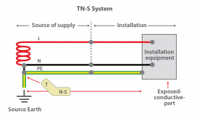
N is bonded to Ground somewhere, not sure if it's at the local transformer (from utility company) or at the main panel.
I think it's called TN-S:
Fig-1-TN-S-System.png

Maybe I confused you because I mentioned MPP LVX inverters, which are split phase / U.S. grid.

I just meant that my inverter has the option to feed the grid with any excess solar power (similar to the LVX, in that manner).
 
I think the inverters are made for your market, so should be fine.
(people trying to use them in the U.S. have difficulty.)
All sharing same ground wires and rod should be good.

If you set up switching of circuits between utility and inverter output, make sure that is done properly, can't have both connected at same time.
Inverters can fail, so it is useful to be able to switch your protected loads panel back to grid.
 
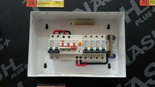
Here is one of a couple interlocks I use:


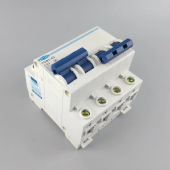
Yours may be DIN rail. I've seen interlocked DIN transfer switches. Some off-brand from China which I wouldn't trust, some name brand from Germany or similar. Something like this:

1661735841319.png
 
Some European electrical service, it is normal to have a GFCI breaker for whole house.
If yours is like that, when using inverter disconnected from grid, that would be disconnected. You might want to put a GFCI breaker after it.

1661742197304.png
 
Some European electrical service, it is normal to have a GFCI breaker for whole house.
If yours is like that, when using inverter disconnected from grid, that would be disconnected. You might want to put a GFCI breaker after it.

View attachment 109150
Yeah, that's the electrical service I have: whole house GFCI.

I am planning exactly that: Putting a GFCI (a.k.a RCD/RCBO) on the inverter output.
If an NG bond is needed, it will be before this GFCI of course, or else it will trip.

What still confuses me relates to my original question: It feels weird to me that my ground will have 2 Neutrals bonded to it (one from grid, and another from inverter output).
 
You just have two systems, separately derived, connected to the same ground wire. Wouldn't want voltage between appliances or plumbing inside the house.
The only funny thing is your inverter needs to disconnect neutral from the grid and connect it to ground. Same is done in the U.S. for mobile systems (RV and boat.)
No current flows in ground, anyway, except if there is a fault. That trips GFCI and disconnects the fault.
 
Hello, i have the same dilemma!
My inverter Voltronic MKS IV 5.6kw supposingly does neutral ground bonding by the manual.

I am planning to use the same ground from the main of the house which is already neutral ground bonded in Greece.
But that ground will also be used in inverter output. I will put also an RCD in the inverter sub panel.

Also do i need 1 ground or i have to bring seperate ground cable to the AC in and AC out?
 
My house actually has 3 phase AC, but my inverter will only be used on one phase.
I mention this because when I look at the 3 phase wiring of my grid, we have 3 "hots" 1 neutral and 1 ground.
All three phases use the same neutral, which is bonded to the ground.

But, in our use case, we are introducing a new neutral which will also be bonded to ground. This scares me a bit, but it seems odd that the manufacturers don't address this issue in the manuals. But on the other hand, they just say that the inverter should be installed by a qualified electrician. So maybe that's just their way to put the responsibility on the customer, without really addressing the issue.

That's why I asked here, because I suppose we aren't the first people to do this kind of setup, although most of the forum members are from the U.S. and AC is different there than in Europe.
Yeah same setup planning here , there isn't clear info here.
When Grid is on, the inverter output neutral is same as the grids (this is my understanding).
Problem happens when you go off grid from what i have understood.
From what i have found my Voltronic does this, bonds neutral-ground automatically when Grid is down.
 
My house actually has 3 phase AC, but my inverter will only be used on one phase.
I mention this because when I look at the 3 phase wiring of my grid, we have 3 "hots" 1 neutral and 1 ground.
All three phases use the same neutral, which is bonded to the ground.

But, in our use case, we are introducing a new neutral which will also be bonded to ground. This scares me a bit, but it seems odd that the manufacturers don't address this issue in the manuals. But on the other hand, they just say that the inverter should be installed by a qualified electrician. So maybe that's just their way to put the responsibility on the customer, without really addressing the issue.

That's why I asked here, because I suppose we aren't the first people to do this kind of setup, although most of the forum members are from the U.S. and AC is different there than in Europe.
Take a look at the thread i opened, not sure gonna help any this topic.
 
Roland describes here how to connect an All-in-one to the loads, in regards to different earthing methods:

In TN-S / TN-C-S he states that we should always use a separate ground, and not connect directly to grid ground.

On one hand this seems odd, but on the other hand, it solves the multiple neutrals (grid and off-grid) being grounded to the same grid ground.

But his schematics only show a scenario where a loads panel is powered either from grid or from inverter. He doesn't exactly address what will happen if only some of the house loads are powered from the inverter and others from grid.

I really can't believe that no one directly addresses this issue, especially for 230v Single phase (European) AC.
But from hours searching online, I still haven't found a definitive answer.
 
Or maybe this is a non-issue?
Can anyone using 230v AC confirm ?

I'm still waiting for my inverter to arrive, but I was thinking of testing like this:

1. Run the inverter in "battery mode" (no AC input connected).
2. Make sure inverter output N-G is bonded (if not, create one externally).
3. Connect a GFCI/RCD to the inverter output (after the N-G bond) and from the GFCI/RCD connect a socket (not connected to anything, just the inverter output L and N via the GFCI/RCD).
4. Connect an AC light bulb to this socket.
5. The bulb should light up without issues.
6. Connect the inverter ground to a house ground.
If the GFCI pops/opens, we have a problem!
The house RCD/GFCI might also trip.
This means that the energy is leaking through ground (and possibly grid's neutral) to somewhere else, and causing an imbalance.
 
Last edited:
Or maybe this is a non-issue?
Can anyone using 230v AC confirm ?

I'm still waiting for my inverter to arrive, but I was thinking of testing like this:

1. Run the inverter in "battery mode" (no AC input connected).
2. Make sure inverter output N-G is bonded (if not, create one externally).
3. Connect a GFCI/RCD to the inverter output (after the N-G bond) and from the GFCI/RCD connect a socket (not connected to anything, just the inverter output L and N via the GFCI/RCD).
4. Connect an AC light bulb to this socket.
5. The bulb should light up without issues.
6. Connect the inverter ground to a house ground.
If the GFCI pops/opens, we have a problem!
The house RCD/GFCI might also trip.
This means that the energy is leaking through ground (and possibly grid's neutral) to somewhere else, and causing an imbalance.
If you don't run the AC in the inverter where is the inverter grounded? Do you plan to create a new ground?

Apparently they discuss it here and it's full of helpful info!

Post in thread 'How does your inverter deal with ground.' https://diysolarforum.com/threads/how-does-your-inverter-deal-with-ground.17138/post-586377
 
Last edited:
I will connect (or at least was planning to...) the inverter's ground to the house ground.
That's where this whole issue started with.
I suppose that my inverter does Neutral to ground bonding internally when in battery mode. Even if it doesn't, I can achieve this bond using the inverter's external relay and an AC contactor.
This isn't the issue.
The issue is that the house ground is also bonded to the house/grid Neutral, and my worries are about having 2 Neutrals (one from grid, one from inverter's NG bond) on the same ground.
 
Back
Top