diy solar

diy solar

Grid tie system with small critical loads battery backup

skyking1

Solar Enthusiast
Joined
Mar 28, 2024
Messages
109
Location
Washington State
I have been reading other threads with a 'critical loads" search.
My initial deployment is 5~8Kw of roof mounted panels, depending on the roof real estate I have.
My goals are to have a minimal critical loads subpanel that can be backed up with an inverter and batteries.
I can keep that load down to 240V@50A, a 6 space box with (4) 15A 120V breakers and a pair of 20's.
That is the breakered load, the actual loads during a power outage would be much less. (Turn off the lights when not in the room, etc. )
Originally I was thinking of microinverters for the built in RSD feature, but the backup aspect may be better served with a string inverter/charger.
I may be wrong on that and would welcome any input.
I will get a net metering agreement and it's a 1:1 with banking from March to March, so there is no advantage for running off the battery bank. I just want the lights to work and the food to not spoil, and my hydronic pumps to work in an outage.
If we are away and all the lights are off, the refrigerator and freezer loads won't be much draw and it could go for days if I prep to keep the loads low.
 
Many ways to skin this cat.

Easiest: get a grid interactive battery backup inverter, eg eg4 18kpv $4900, solark 15k $7000. Or wait for the new growatt sph 10000tl for about $2600
 
An 18kpv or Sol-Ark 15k would be massive overkill for a minimal critical loads subpanel. Would recommend performing at least a minimal power demand study of the proposed "critical" circuits to quantify your needs but based on the description something like a Schneider 4048 would be more than adequate. If net metering is your goal then a UL1741SB compliant inverter is required.

Alternatives: SMA, Outback, or Enphase IQ8 microinverter system with Enphase batteries.
He said 50a at 240v
 
I originally did something similar. Have 9k of PV on the roof and a SolarEdge grid tie system with 1:1 net metering. Put up a Growatt SPF6000DVM because I needed 240 for the well pump, and 12 Kwh of batteries. Basically acted as a UPS with charging from the grid. Your more complicated and potentially expensive item is a sub panel to break out your critical loads.
 
Easiest: get a grid interactive battery backup inverter, eg eg4 18kpv $4900, solark 15k $7000. Or wait for the new growatt sph 10000tl for about $2600
Or Amensolar N3H-X10-US available now for $2200.

There are other grid interactive, 10 KW class, sub $3K, string inverters out there.

Add panels and battery to complete the system.

If you want fast backup (like a big UPS), then you have to find units with fast switchover times. If the inverter can pick up the critical loads in under, say, 15 ms, then your devices won't reboot or reset.

Mike C.
 
An 18kpv or Sol-Ark 15k would be massive overkill for a minimal critical loads subpanel. Would recommend performing at least a minimal power demand study of the proposed "critical" circuits to quantify your needs but based on the description something like a Schneider 4048 would be more than adequate. If net metering is your goal then a UL1741SB compliant inverter is required.

Alternatives: SMA, Outback, or Enphase IQ8 microinverter system with Enphase batteries.
Thanks. I do think the loads can go down on the critical loads panel. I need to get the minimal hydronic pumps sized and go forward from there.
 
I originally did something similar. Have 9k of PV on the roof and a SolarEdge grid tie system with 1:1 net metering. Put up a Growatt SPF6000DVM because I needed 240 for the well pump, and 12 Kwh of batteries. Basically acted as a UPS with charging from the grid. Your more complicated and potentially expensive item is a sub panel to break out your critical loads.
Fortunately this is new construction, so It will be wired from the start for that subpanel.
One thing about the All In Ones that bothered me was taking that critical loads grid power through the AIO in the EG4. I have read some about using a relay so if the AIO needs service, it is not sitting in the path for the grid power directly.
 
Or Amensolar N3H-X10-US available now for $2200.

There are other grid interactive, 10 KW class, sub $3K, string inverters out there.

Add panels and battery to complete the system.

If you want fast backup (like a big UPS), then you have to find units with fast switchover times. If the inverter can pick up the critical loads in under, say, 15 ms, then your devices won't reboot or reset.

Mike C.
There are several available in the 10kw class. I didn't mention them because I wouldn't consider them
 
One thing about the All In Ones that bothered me was taking that critical loads grid power through the AIO in the EG4. I have read some about using a relay so if the AIO needs service, it is not sitting in the path for the grid power directly.
You should have a bypass option so you can run the critical loads panel from grid directly while isolating the inverter.

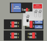
A relatively simple way to do this is an interlock breaker in the critical panel. The grid feeds the main breaker which is usually off, the inverter feeds the inverter load breaker in the the top right column, usually on, and there is a metal slider that prevents both from being on at the same time.

For example:


1715781833519.png

If the inverter needs service or has failed, turn off the inverter load breaker, slide the interlock, turn on the main grid breaker. This puts the critical load panel directly onto the grid and now the inverter can be serviced while those loads are satisfied.

To be clear, the critical panel main breaker is not the "main" breaker, it is fed by another breaker in the main panel.

An alternative is to put in a two position transfer switch. These are fairly ugly and big, though.

Mike C.
 
Last edited:
Thanks that is a fairly elegant solution. Yes I know the critical loads gets a breaker out, and in your example the inverter into the main panel gets a separate breaker going in.
In the pass through scenario the same breaker in the main panel serves both purposes. That was the configuration I wanted to avoid.
 
I always prefer an interlock over a transfer switch. But it can be an issue if you also feed the grid through the inverter. It creates Parallel neutral paths.
Which means that you will have neutral current running through the inverter, even when bypassed. This possess a hazzard when working on the inverter.
 
Thanks Tim. These are the things I want to avoid. It seems like a seperate unit like the Schnieder has merit in that situation.
 
Thanks that is a fairly elegant solution. Yes I know the critical loads gets a breaker out, and in your example the inverter into the main panel gets a separate breaker going in.
In the pass through scenario the same breaker in the main panel serves both purposes. That was the configuration I wanted to avoid.
I don't understand what you're trying to avoid here.
 
In the pass through scenario the same breaker in the main panel serves both purposes. That was the configuration I wanted to avoid.
No, there are two breakers in the main panel.

One breaker feeds the critical panel "main" breaker. It is the grid only path.

Another breaker, usually at the end of the bus bar, serves the inverter grid input. It is the inverter path breaker.

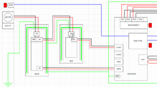
My diagram:

1715783580338.png

In "inverter" mode:

Main panel critical panel breaker: ON or OFF (doesn't really matter)
Main panel inverter grid breaker: ON
Critical panel "main" breaker: OFF (interlocked)
Critical panel inverter load breaker: ON (interlocked)

In "grid only" mode:

Main panel critical panel breaker: ON
Main panel inverter grid breaker: OFF (to fully isolate)
Critical panel "main" breaker: ON (interlocked)
Critical panel inverter load breaker: OFF (interlocked)

All neutrals are tied together, all grounds are tied together. Only the main panel has ground neutral bond.

In "grid only" mode, the inverter is isolated from all AC connections and can be serviced safely.

Mike C.
 
I always prefer an interlock over a transfer switch. But it can be an issue if you also feed the grid through the inverter. It creates Parallel neutral paths.
Which means that you will have neutral current running through the inverter, even when bypassed. This possess a hazzard when working on the inverter.
How so?

If there is a second neutral path, like my diagram above, then disconnecting neutral at the inverter doesn't result in any meaningful voltage on the neutral conductors.

The inverter diagrams show neutral loops when wired up per their manuals. How else would you wire it?

I must not be understanding the issue, please elaborate.

Mike C.
There are two neutral paths in parallel.
1. From the main panel, through the inverter, to the sub panel.
2. From the main panel, directly to the sub panel.
These two paths will always be sharing the neutral current.
The correct way to do this is with a single neutral to each point, from a central connection.
Example:
A wire trough under the 3 pieces of equipment. (Main panel, sub panel, inverter)
A neutral terminal block in the trough. And a single neutral from the terminal block to each piece of equipment.
 
There are two neutral paths in parallel.
Each of which is capable of carrying the full load.

These two paths will always be sharing the neutral current.
Unless one becomes disconnected. Then the other carries all the load and is rated for it.

The correct way to do this is with a single neutral to each point, from a central connection.
I'm still unaware of the hazardous condition if this isn't the case.

The wiring diagrams in the manuals don't seem to require the wiring layout you propose.

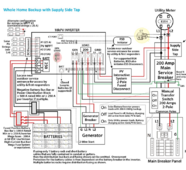
For example, EG4 18KPV:

1715792395569.png

Neutral goes through the inverter and through the 2 pole transfer switch (thus neutral is not switched). Why is that wrong?

Mike C.
 
Each of which is capable of carrying the full load.


Unless one becomes disconnected. Then the other carries all the load and is rated for it.


I'm still unaware of the hazardous condition if this isn't the case.

The wiring diagrams in the manuals don't seem to require the wiring layout you propose.

For example, EG4 18KPV:

View attachment 215559

Neutral goes through the inverter and through the 2 pole transfer switch (thus neutral is not switched). Why is that wrong?

Mike C.
You have to consider the source of the information, before you take it as qualifying.
EG4 is still learning and growing.
And China is not a good source.
They don't know what they don't know.
Whenever you introduce a second source, there are always special considerations.
and parallel paths should always be avoided.
i explained why, above.
I can only suggest the safest way of doing it. But in the end, it's up to you to decide how to proceed.
 
Back
Top