diy solar

diy solar

Grid tie system with small critical loads battery backup

This would also require the interlock in the main panel be set to bypass.
There is no interlock in the main panel.

If your backup panel has all loads on one phase, then the neutral will have 60 amps in it.

The breaker feeding the circuit will also limit the neutral current.
There are two breakers feeding these combined neutrals.

The neutral from main to backup can have both the backup panel loads (in grid mode) and the inverter acting either as load (battery charging) or source (PV generation). In unbalanced ways, this can also create 60 amps.

You could get 120 amps in the neutral with the common tie point shared neutral concept.

You can't have more current on the neutral, than what is on an individual leg.
You can because the neutral is shared among TWO circuits now. The SUM of those breakers is in play.

Mike C.
 
Only reason for interlock on main panel is if you want to feed one of its loads from the inverter, during a grid failure.
Correct.

An illegal way to do this is to:

1. Turn off main panel main breaker. this disconnects you from the utlity.
2. Turn off every breaker in the main panel you do not want to power.
3. Turn off the main panel inverter breaker.
4. Turn on the backup panel grid breaker.
5. Defeat the backup panel interlock and turn on both the backup panel main breaker and the inverter load breaker.

A possible legal way to do this is to make another link between backup and main panel. This requires a source breaker in the backup panel, a back feed breaker in the main panel, and an interlock between main panel main breaker and the backup panel back feed breaker. This back feed breaker would have to be in the top right breaker slot due to the interlock requirements.

Your interlock on sub-panel can be a bypass, direct to grid, for inverter repair. Normally fed by inverter so you have UPS for critical loads.
That is what it is, a way to put the backup panel on grid in case of inverter failure or inverter service. If you didn't have this bypass, then the circuit becomes easier but you have lost redundancy.

If you never connect anything to Load2, neutral won't be overloaded. Inverter will charge with L1/L2, zero current on N. I used two separate N wires, so they won't be overloaded regardless.
I'm not sure we can assume balance on the inverter demands on the grid input. Seems logical, but it is still an assumption.

My concern with relying on inverter is there are failure modes that can leave it shut down. In some ways, grid is a more reliable supply for freezer.
I would like a deadman switch that falls back to grid if inverter output is off.
I thought about some sort of relay that drops out if the inverter load output falters. The relay would transfer backup panel to grid if/when the inverter load output fails.

A downside is that the relay will take power to energize nearly all the time. It would remove the interlocks on the backup panel and would make fail over automatic.

It has the same neutral question as the interlocks, though.

Mike C.
 
My concern with relying on inverter is there are failure modes that can leave it shut down. In some ways, grid is a more reliable supply for freezer.
I would like a deadman switch that falls back to grid if inverter output is off.
In my scenario I want grid power that fails over in a grid outage. I don't want to run on inverter and batteries as the normal mode of operation. I am thinking this is best handled with a relay to the subpanel with a delay for re-making to grid.
I do not care about UPS-like fail over.
If the power goes out, I am happy if 5 seconds later the fridge and freezer get some clean power.
When the power comes back on, often there is a little drama so I would want to delay that return to service.
If I have some electronics that want to be protected by a UPS I will have them on an individual UPS.
 
Can I get this device in a UL version?

1715874878669.png

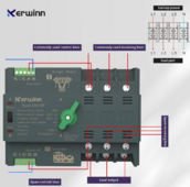
Put this before the backup panel and have it automatically switch from grid or inverter. You can switch it to manual to force the choice, or it can be set to automatically switch on source failure. Rates 100 amps. Uses a servo motor, so not fast

Basic operation of a similar device:


The Europeans have so much nicer stuff sometimes.

Mike C.
 
What I keep seeing is, this critical load panel is not an automatic fail over the way people keep drawing it.
It's automatic through the AIO.
The interlock is for a bypass for maintenance. (Which is always recommended)
 
OK. An AIO string inverter seems to be cost effective when compared to microinverters and a piece of backup hardware.
The load paths from grid to critical load panel is linear and goes through the AIO.
If the grid fails the AIO starts up and supplies only the critical load panel.
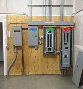
If I build the panels up on a gutter like this,
Image from reddit.
my main power is coming up from basement slab , on right tagged with some red.
AIO is green,
Subpanel is blue on left.
In the gutter I run the single neutral path and the ground path through there and tee off of them where I tagged it with Tan, using a bus bar for ground and a Polaris for neutral.
This ensures no neutral loop condition.

gutter.jpg

In the inside premise wiring, I propose using a different color of wire jacket for the critical loads circuits. Say white for regular and yellow for the Critical Loads (CR)
Where the CR lighting circuit occupies the same duplex switch plate as another circuit, use a common plate but a divided box so there is no possibility of looping there.
I say this because I just want those main navigation lights to work on backup, not every light circuit in the house. This helps with the " load to be served" rules.
If I try to serve them all off CR, the thing gets bloated for no need.

@timselectric does this look like a good plan to pass inspection without a lot of grief?
My big concern is the regulatory certification for the AIO. I don't want to put in a functional piece that does not pass all the requirements of the 2020 NEC.
I am in Washington state and they are at NEC 2020 until sometime in 2025 TBD.
I will do everything possible to get this done in 2024 :)
 
The inverter can be a load to the grid and a source to the backup panel at the same time.
Not the neutral.
Any loads in the backup panel will be fed by either the grid or the inverter. (Not both)
No, it is two, grid and load.
Not when referring to the neutral.
There is no interlock on grid and load to the inverter. They both operate at the same time.
Correct
There is no interlock that prevents the inverter from using the grid connection while the backup panel uses the grid.
Correct, through the inverter.
But there should be an interlock at the main panel. So that inverter and bypass are not both on.
The only interlock is the backup panel can be powered from the main panel or from the inverter load output. That is the only interlock in the system.
I thought that you mentioned an interlock in the main panel.
But I see that you just detailed the operation as the same.

>In "grid only" mode:

Main panel critical panel breaker: ON
Main panel inverter grid breaker: OFF (to fully isolate)
Critical panel "main" breaker: ON (interlocked)
Critical panel inverter load breaker: OFF (interlocked)<

The inverter can and *must* be able to operate as a source and a load at the same time. This is fundamental to its operation.
Again, not in regards to the neutral.
It's only a return path for whichever the source of the load is, at the time.
#1 violates the wiring diagrams in the inverter manual. They always show the load neutral connection being used. Not following the manual violates the certifications.
I disagree
#2 creates a neutral which has a loop. The loop is closed at the inverter with the grid neutral and load neutral are assumed to be internally connected.
I agree
But you seemed bound to running parallel paths. I gave you one that wouldn't hurt anyone.
Not really. I'm far more confused now than when we started because I don't actually understand what you think is the right connections and/or what you are telling me violates code, the manual, or both.
The manuals wiring diagrams were fine. Until they tried to add the bypass switch. This is where they introduced the multiple neutral paths.

I'm sorry that I can't explain it in a way that you would understand.
I'm running out of ways to say it.
I feel like we are just repeating ourselves, back and forth.
You really have to understand how current flows. Especially regarding the neutral.
I guess, that you should just do what you feel comfortable with.
And hopefully the parallel neutral path will never be a problem.
 
Some AIO may have NC DPST relay to grid and would pass it through if inverter is down.
My Sunny Island has NO DPST relay. It has to operate for 5 minutes monitoring grid before connecting.

A DPDT relay would have the functionality desired, keep loads fed through AIO/UPS so long as it is operating, fall back to grid if AIO fails. However, I don't like DT relay to switch between two sources. I've had relays draw an arc and short the two inputs. I want two separate interlocked relays, one opening for a few seconds before allowing other to close.

Or, a big DPDT knife type transfer switch, spring loaded to return to grid when solenoid or motor is unpowered.

Relays do draw current while holding. But pull-in current requirement is much higher than what is needed to hold.
Relays (and drivers) are available with economizer function for DC coil, reduce to a couple percent as much power for hold
AC coils inherently have economizer functionality (but I haven't measured). When pulled in, core contacts to complete magnetic circuit, and inductance becomes much higher so current draw lower. Need to put a scope current probe on it to test.

Loops? I don't care about no stinkin' loops!
Current will take the path of lowest impedance, Z = sqrt(R^2 + X^2) = |<complex impedance R + jX>|
So long as each path has sufficient ampacity, I ain't worried.
 
OK. An AIO string inverter seems to be cost effective when compared to microinverters and a piece of backup hardware.
The load paths from grid to critical load panel is linear and goes through the AIO.
If the grid fails the AIO starts up and supplies only the critical load panel.
If I build the panels up on a gutter like this,
Image from reddit.
my main power is coming up from basement slab , on right tagged with some red.
AIO is green,
Subpanel is blue on left.
In the gutter I run the single neutral path and the ground path through there and tee off of them where I tagged it with Tan, using a bus bar for ground and a Polaris for neutral.
This ensures no neutral loop condition.

View attachment 215801

In the inside premise wiring, I propose using a different color of wire jacket for the critical loads circuits. Say white for regular and yellow for the Critical Loads (CR)
Where the CR lighting circuit occupies the same duplex switch plate as another circuit, use a common plate but a divided box so there is no possibility of looping there.
I say this because I just want those main navigation lights to work on backup, not every light circuit in the house. This helps with the " load to be served" rules.
If I try to serve them all off CR, the thing gets bloated for no need.

@timselectric does this look like a good plan to pass inspection without a lot of grief?
My big concern is the regulatory certification for the AIO. I don't want to put in a functional piece that does not pass all the requirements of the 2020 NEC.
I am in Washington state and they are at NEC 2020 until sometime in 2025 TBD.
I will do everything possible to get this done in 2024 :)
If I understand correctly. You won't be installing any bypass.
Your system will just be grid (main panel) to AIO to Critical loads panel.
If this is correct, you don't need to do anything special.
The wiring is linear and simple.
I'm sorry if the discussion drifted away from your needs.
 
No worries. I will install that bypass breaker in the critical loads, and serve it with a breaker from grid, so I can yank the AIO out of there with minimal drama. None of that makes loops if done right.
Clicky clicky and then de-energize the AIO and send if off or even change it out for the latest and greatest, etc.
Thank you @Hedges for this imporant point!
Some AIO may have NC DPST relay to grid and would pass it through if inverter is down.
That is a must-have criteria. It needs to just send grid. Does anybody have any recommendations for that?

That is exactly why I was proposing a simple relay.
 
I think this was part of the discussion and may have gotten lost.
There will be a neutral wire from the main panel to the subpanel's neutral bus bar.
There will be a ground wire from the main panel to the subpanel's ground bus bar.
The neutral and ground bus bars in the subpanel are separate bus bars and are not bonded or connected.

How is the neutral from the AOI which is bonded to the neutral bus bar in the subpanel handled when the AOI is pulling power from the grid or from the batteries/array.

Is there a possibility of the subpanel having two neutral paths back to the main, the first hardwired and the second through the AOI
 
Some AIO may have NC DPST relay to grid and would pass it through if inverter is down.
This only works if the "inverter is down" detection logic works. If the invert fails such that it still energizes that relay, your backup panel is dark and the relay won't drop to grid.

Ideally this means this relay is powered by the inverter AC output directly so there is no firmware or logic in the decision, but this has negative consequences in that it may chatter if the inverter output is unstable (blips on and off). Thus you usually have some firmware that observes the voltages a while before switching, and thus this fail over relay can fail in firmware.

A DPDT relay would have the functionality desired, keep loads fed through AIO/UPS so long as it is operating, fall back to grid if AIO fails. However, I don't like DT relay to switch between two sources. I've had relays draw an arc and short the two inputs. I want two separate interlocked relays, one opening for a few seconds before allowing other to close.

Or, a big DPDT knife type transfer switch, spring loaded to return to grid when solenoid or motor is unpowered.
That is what is nice about the DIN ATS I pictured above. It has a motor to drive the switch contacts to either input. Thus no power usage during operation (big relays are power hogs). And this also means it can have beefy contacts since the motor can drive them easily. It also provides manual control, too.

I really wish I could find something like that in a UL certified way. That would make things way better since it would add automatic redundancy, remove the breaker interlock on the backup panel, and free up 2 breaker slots in the backup panel.

Loops? I don't care about no stinkin' loops!
Me, neither, this is lot of ado about nothing that has no meaningful safety or functional impact.

Mike C.
 
Not the neutral.
Any loads in the backup panel will be fed by either the grid or the inverter. (Not both)
This is getting ridiculous.

Let's assume what I think you are advocating, a single point neutral bar with 3 connections: main panel, backup panel, inverter (combined grid and load neutrals into one wire).

The neutral wire to the backup panel is only the loads on the backup panel, No problem there.

The neutral wire from neutral bar to the main panel is potentially the combination of the inverter grid neutral current *AND* the backup panel neutral current (if the backup panel is in grid mode). TWO CIRCUITS, ONE NEUTRAL.

The neutral wire from neutral bar to the inverter is potentially the combination of the inverter grid neutral *AND* the inverter load neutral currents (if the backup panel is in inverter mode). TWO CIRCUITS, ONE NEUTRAL.

How is it that you don't see that?

#1 violates the wiring diagrams in the inverter manual. They always show the load neutral connection being used. Not following the manual violates the certifications.
I disagree
Not connecting to the inverter load neutral is an obvious and clear violation of the manual wiring diagrams. The UL certification is based on installing the inverter per the manual.

And hopefully the parallel neutral path will never be a problem.
There is no mechanism for it to be a problem.

I see all sorts of possible problems with a shared neutral for two circuits, however. Or not connecting the neutral on the inverter load.

Mike C.
 
That is exactly why I was proposing a simple relay.
My inverter, on failure, will not drop a relay that connects GRID to LOAD automatically. Or so says the reseller.

A relay is not simple, it turns out. Expensive, power hungry, complex to switch lines under load, etc.

The DIN rail ATS I showed above would work nicely, but lacks US approvals.

Mike C.
 
I gave you the code reference.
And safety is the reason.
I'm sorry that you can't grasp this.
No unsafe event has been described for a neutral loop that is 6 ft long. A redundant neutral connection sounds safer than using one neutral for two circuits.

We have both quoted code and neither of us can make the system totally complaint with it. I can't avoid the neutral loop, you can't confine the neutral wire to only one circuit.

So there we are.

Mike C.
 
My inverter, on failure, will not drop a relay that connects GRID to LOAD automatically. Or so says the reseller.

A relay is not simple, it turns out. Expensive, power hungry, complex to switch lines under load, etc.

The DIN rail ATS I showed above would work nicely, but lacks US approvals.

Mike C.
what line is it switching under load?
If grid stops, there is no longer any current.
Switch it, and turn on the inverter. I don't need <15 Ms UPS action.
I also don't have huge needs in terms of current.
 
Back
Top