diy solar

diy solar

Help required to estimate VOC of panel strings compatible with inverter

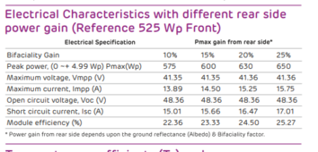
Secondly, as shown in attachment, yesterday, it was over caste, cloudy day. I noticed that around 11 am, the system reached 5330 W (Installed capacity is 5220 W). Since, the panels are bifacial, I guess, due to scattering, the panels were producing from lower side as well.
The gain could also be on top side due to cloud lensing , and there could be some gain from being cold.

IOW the power can exceed nameplate on a monofacial too since the specs are not a hard limit. If you moved a solar panel to a closer orbit around the sun it will generate more (assuming it stays at normal temp).

I believe white rocks or gravel are standard ways to try to help out bifacial. That gives diffuse scatter which may be better across more hours of the day than a reflector at a constant angle. Also you need to keep the maintenance overhead in mind, and the fact that solar panels are really cheap anyway.
 
I have not worked with bifacial, but very good point that if it delivers extra current, expect somewhat higher voltage!
(If data sheets quote added wattage from bifacial, do they quite added voltage?)
 
I have not worked with bifacial, but very good point that if it delivers extra current, expect somewhat higher voltage!
(If data sheets quote added wattage from bifacial, do they quite added voltage?)
Dear Hedges
I need your opinion about connecting my 9 JA solar panels (580W) with Kostal Piko 4.6. The details of the inverter and panels are as under

JA solar specs
Pmax 580
Voc 48.18
Vmp 40.42
Isc 15.21
Imp 14.35


Inverter specs
VDC Max 1000
Rated vdc 600
Isc 13.8 (mentioned on inverter)
Imp 11


The reason for asking this question is the difference in IDCmax and ISC of inverter and panels.
In case I can hook the panels, what would be the highest output of these panels under good conditions?


Regards
 
VDC max impacts how many you can have in series. Voc * number of panels * cold temperature compensation must be lower than that. And going higher is quite often instant death for the inverter.

Those panels have Isc exceeding your inverter , this is a less strict number but some inverters might fail in good sun conditions.

Use PVwatts to compute the expected yield
Let me explain my position
I haven't problem with inverter's voc as it is beyond the 9 panel voc (433vdc). I have issue with inverter's Isc and Idcmax which are 13.8 and 11.
Q1. Panels have Isc of 15.2A. so, will it hurt the Inverter or not?
Q2. If the inverter is happy with 9 panels in series and can accept these panels, under ideal conditions, will the inverter pull current from panels equal to Isc or equal to Idcmax.
Your thoughts please
 
I haven’t heard of this number. It will pull Impp as appropriate to the lighting and temperature conditions.

Isc safety is more complex and it depends on the specific inverter. You have to sort of get lucky and wait for someone who has your inverter (which sounds rare). Going above Isc is generally believed to break reverse polarity protection. On Victron it is believed / reported by Victron that there are failure modes that will depend on Isc being respected.

That inverter is ill suited to the cell size you have. It’s for the previous generation of smaller cells.

If you insist on using this GTI, maybe put a breaker sized at 1.25*Isc or 1.53*Isc of the inverter. Probably 1.25
 
Both Isc and Imp exceed inverter spec for max Isc.
Best case inverter is able to operate near Isc, but that would be greater heating of its transistor than normal. You'll get significantly less than full wattage from panels in full sun.
If it does work OK, in reduced sun it should perform well.

Better to get lower current panels or higher current inverter.
The Sunny Boys I have used before supported max 10A Imp per MPPT, while new Sunny Boy Smart Energy supports 15A, could work with these panels.
But it allowed MPPT A and MPPT B to be paralleled, good for 20A and 30A respectively.

Does your inverter have multiple MPPT input, and can they be paralleled?
Please see the attachment. It has two mppts.. I don't what do you mean by parallel here.
 

Attachments

  • Screenshot_20240524-172754.jpg
    Screenshot_20240524-172754.jpg
    111.3 KB · Views: 4
I haven’t heard of this number. It will pull Impp as appropriate to the lighting and temperature conditions.

Isc safety is more complex and it depends on the specific inverter. You have to sort of get lucky and wait for someone who has your inverter (which sounds rare). Going above Isc is generally believed to break reverse polarity protection. On Victron it is believed / reported by Victron that there are failure modes that will depend on Isc being respected.

That inverter is ill suited to the cell size you have. It’s for the previous generation of smaller cells.

If you insist on using this GTI, maybe put a breaker sized at 1.25*Isc or 1.53*Isc of the inverter. Probably 1.25
Actually, I have already gone through a problem with another inverter (hybrid one) who's charge controller failed and is now under repair. That inverter supported Isc of 27A and panels were 6S2P panels were hooked with it. Since, panels had Isc of 15.2 (30 in parallel mode), the Inverter couldn't handle it and gave error. That's why I am asking about this inverter as I don't to destroy another one. Instead, I would like to buy new one with matching specs as those of panels.
 
You're in luck.
It says right there max input with parallel connection (DC1 + DC2) 22A.

It means connect DC1 negative to DC2 negative, connect DC1 positive to DC2 positive.
Then it can take one series string of your panels.

I think it might work with two series strings, then paralleled (e.g. 15s2p) if the two strings are oriented differently - that way they don't produce max current at same time. Having 90 degree angle between them would be good, area presented to sun and current produced 0.7x as much.

Although, bifacial could make it higher.

Voc 48.18 x 1.15 (for cold weather) = 55.4V
Vmp 40.42

VDC Max 1000
Rated vdc 600

1000V / 55.4V = 18.05, up to 18 panels in series

600V / 40.42V = 14.8, about 15 panels in series is a good fit by volts.

Imp 14.35

40.42 x 15 x 14.35 = 8700W (STC) from one string.

What is wattage rating of inverter?
 
I read this as, it has a mode where the two MPPTs are locked together, so both inputs can take the output from same string. Probably similar to what you are saying.

This mode is not available in all brands.

Wasnt sure if this mode has a different min start voltage. I think the start voltage is the same and this is just telling you the voltage you need to max out the inverter

1716583175762.png

Unfortunately this does not have Isc spec which I think is what was confusing you
It says right there max input with parallel connection (DC1 + DC2) 22A.
 
I think 9s in paralleled MPPT mode is 100% safe and should be able to max out the inverter since the 22A DC in spec is usable operating current, and that is lower than Isc.

And 22A is way higher than what your panel can push out
 
You're in luck.
It says right there max input with parallel connection (DC1 + DC2) 22A.

It means connect DC1 negative to DC2 negative, connect DC1 positive to DC2 positive.
Then it can take one series string of your panels.

I think it might work with two series strings, then paralleled (e.g. 15s2p) if the two strings are oriented differently - that way they don't produce max current at same time. Having 90 degree angle between them would be good, area presented to sun and current produced 0.7x as much.

Although, bifacial could make it higher.

Voc 48.18 x 1.15 (for cold weather) = 55.4V
Vmp 40.42

VDC Max 1000
Rated vdc 600

1000V / 55.4V = 18.05, up to 18 panels in series

600V / 40.42V = 14.8, about 15 panels in series is a good fit by volts.

Imp 14.35

40.42 x 15 x 14.35 = 8700W (STC) from one string.

What is wattage rating of inverter?
I have 9 panels right now. So, what you mean is that I should bring down the 9 panels in series and put the -tve and +ve terminals of solar array with mpp1 and st same time with mppt2? In this way it would be safe having Isc above 26A? I'm understanding right?
 
You're in luck.
It says right there max input with parallel connection (DC1 + DC2) 22A.

It means connect DC1 negative to DC2 negative, connect DC1 positive to DC2 positive.
Then it can take one series string of your panels.

I think it might work with two series strings, then paralleled (e.g. 15s2p) if the two strings are oriented differently - that way they don't produce max current at same time. Having 90 degree angle between them would be good, area presented to sun and current produced 0.7x as much.

Although, bifacial could make it higher.

Voc 48.18 x 1.15 (for cold weather) = 55.4V
Vmp 40.42

VDC Max 1000
Rated vdc 600

1000V / 55.4V = 18.05, up to 18 panels in series

600V / 40.42V = 14.8, about 15 panels in series is a good fit by volts.

Imp 14.35

40.42 x 15 x 14.35 = 8700W (STC) from one string.

What is wattage rating of inverter?
Its max output wattage is 4600 w
 
I think 9s in paralleled MPPT mode is 100% safe and should be able to max out the inverter since the 22A DC in spec is usable operating current, and that is lower than Isc.

And 22A is way higher than what your panel can push out
You mean I could use this inverter in parallel mode with single string being hooked with both mppts?
 
I read this as, it has a mode where the two MPPTs are locked together, so both inputs can take the output from same string. Probably similar to what you are saying.

This mode is not available in all brands.

Wasnt sure if this mode has a different min start voltage. I think the start voltage is the same and this is just telling you the voltage you need to max out the inverter

View attachment 217413

Unfortunately this does not have Isc spec which I think is what was confusing you
The Isc rating is written on the Inverter itself and not mentioned in specs datasheet. Here I'm attaching inverter pics with datasheet
I read this as, it has a mode where the two MPPTs are locked together, so both inputs can take the output from same string. Probably similar to what you are saying.

This mode is not available in all brands.

Wasnt sure if this mode has a different min start voltage. I think the start voltage is the same and this is just telling you the voltage you need to max out the inverter

View attachment 217413

Unfortunately this does not have Isc spec which I think is what was confusing you
 

Attachments

  • Screenshot_20240524-174058.jpg
    Screenshot_20240524-174058.jpg
    46.3 KB · Views: 3
You mean I could use this inverter in parallel mode with single string being hooked with both mppts?
Yes but you need to turn on that mode in the config. Otherwise they could fight, if running in independent mode, because independent trackers may try to operate at different voltages

And “both MPPTs” may be the wrong way to express this but you probably understand what is going on.
 
Also you need to be mindful of failure modes/transient modes where only one input can sink the current from a string. IE you want to turn off a disconnect that disconnects both at the same time, when you do any wiring changes
 
Back
Top