diy solar

diy solar

Help with 2s4p setup

TheCoachStone

New Member
Joined
Feb 12, 2021
Messages
127
Location
Birmingham, AL
Hello everyone.

I have a LV6048 and I have found some local panels I want to try.

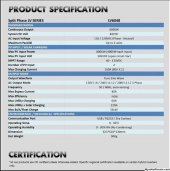
The LV6048 - lv6048.JPG
The panels are REC360AA - REC360AA.JPG

By my math, a 2s4p would give me

  • Solar Array Wattage: 2880W
  • Temperature Compensated Array Voltage: 98V
  • Controller Output Amperage: 50A
  • Array Short Circuit Amperage: 39.28A
  • Max Series Fuse Rating: 15A
So, would a 2s4p for each input be the best way to wire these?
 
Last edited:
Yes although with two input consider consider 2x 2s2p and avoid the string fuses.
Also gives flexibility to point one set south and the other set a bit west depending on conditions.
 
Yes although with two input consider consider 2x 2s2p and avoid the string fuses.
Also gives flexibility to point one set south and the other set a bit west depending on conditions.
unless he plans another set of PV in the (near) future, then may be better to set this up as stated, and not have to change it/wire later.
 
I would not go higher than 2S. BTW, that 98V temperature compensation is only good to ~ freezing. As the temperature goes lower and lower, the voltage goes up and up. But, in Alabama, I suppose you aren't likely to see lower than ~ freezing anyway.

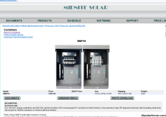
If it was my system, I'd wire each series string to it's own breaker, and forget about fuses completely. A 6-bay Midnight combiner is what I have, and you could also use. Having each string separate is great when you have to do troubleshooting.
1695224129065.png
 
2-pole breaker per PV string, or per combined home run, lets you disconnect both PV+ and PV- so that voltage source is isolated from AIO when working on it.

Note that PV input of AIO may still have voltage present on it, coming from battery & inverter or AC input. Shut everything off and test for DC and AC with meter before working on it.

Be sure to run a ground wire from AIO to frames of PV panels. Otherwise, they may be an AC shock hazard as many people have discovered.
 
I would not go higher than 2S. BTW, that 98V temperature compensation is only good to ~ freezing. As the temperature goes lower and lower, the voltage goes up and up. But, in Alabama, I suppose you aren't likely to see lower than ~ freezing anyway.

If it was my system, I'd wire each series string to it's own breaker, and forget about fuses completely. A 6-bay Midnight combiner is what I have, and you could also use. Having each string separate is great when you have to do troubleshooting.
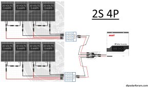
View attachment 168477

2S4P.jpg.84787ed4c0f251a262c76536889a8135.jpg

1. Is this correct?
2? The combiner box would go where here?
 
The rectangle with fuses in it would be the combiner box. This shows two, maybe all in one box. Physically located where convenient and appropriate for the weather. Is this for a house or for an RV? For a house there would be requirements regarding location of disconnects. And other requirements.

Typically combiner box transitions to screw terminals and you don't use MC4 connectors after it. This drawing has 2s4p all combining down to one MC4 connector, so 5A x 4 = 20A though the connector. Some connectors can take that, some can't.

There is a big problem mixing different brands of "MC4" connector, resulting in failures and fires. The only UL listed connections are between UL listed connectors of same brand, or pairs of brands that were UL listed and tested together.

20 volts x 5 amps = 100W panels. Still being sold, but larger higher voltage panels tend to be cheaper per watt.
Oh, you showed data for a 360W panel, that's much better! (this was just an example array.)

Inverter has 2 PV inputs. It has MPPT. Do you know if it has 2 MPPT, or is that just two pairs of terminals for PV, wired in parallel for one MPPT?
If two MPPT, you can put 2s2p into each MPPT, no OCP required. One 2-pole breaker per MPPT would be good for isolation.
It does have 2 MPPTs - https://shopsolarkits.com/products/mpp-solar-lv6048 - I had to check.

I should run 2 2s2p not 2s4p?
 
Yes, 2s2p into each separate MPPT.

You could use MC4 "Y" cables, try to have same brand connector (probably not documented).
What I do is cut an extension cable in half to make pigtails, put them through compression glands into a box, join wires to THHN/THWN and run through conduit the rest of the way. I used wire nuts initially, but SMA recommends against those so now Ideal set-screw nuts.

A box with DIN rail could have a couple 2-pole breakers as isolators. Not supposed to put two wires in one screw terminal (although it usually seems to work), so maybe a crimped ferrule or nuts or other wire splices.
Ok, so 4 2s2p into the combiner box and then into 2 wire pairs - 1 into each input?
 
"4 2s2p" ?
Do you have 16 panels?

"would a 2s4p for each input ..."
Apparently so.

OK, 16 panels, 8 per MPPT input, each input gets 2s4p.
In that case you do need OCP for each string.
 
"4 2s2p" ?
Do you have 16 panels?

"would a 2s4p for each input ..."
Apparently so.

OK, 16 panels, 8 per MPPT input, each input gets 2s4p.
In that case you do need OCP for each string.
Ok, this is a serious question - would 8 panels be enough? I can buy 8 or 16. I just want to push the inverter as far as I can.
 
Each MPPT can handle 4K so that’s about 8-10 panels per string

Could do 2s5p in to each MPPT. With that low a max VOC of 150v you are kinda locked into 2sXp configurations.

What is the storage and load situation? Can you battery bank take 160a of charging current? I think you’d want at least 400ah at 48v if you were to max out the PV inputs.

Granted if you have panels all connected but leave a string isolated until you get more storage down the road.
 
You can push the inverter 40% further with strings oriented 90 degrees to each other (hypotenuse of right equilateral triangle is max area presented to sun).
You may be able to over-panel further, for off-season and cloudy days.
Panels are relatively cheap, especially if used.
 
I have run 2S 3P with my MPP 6048's ,but not 4P or 5P because the current gets so high with the 440W panels.
your 360's are about 10A per parallel set, 2S-3P about 30A, 2S-4P about 40A and 2S-5P about 50A.
so you would need large enough wire from the combiner box to the MPP inputs on the inverter.
The DC wire size calculator I use, based on 30 feet, max 75C cable rating, 3% voltage drop:
30A = 10AWG
40A= 8AWG
50A= 8AWG

if you go 2S-2P no fuses requred
if you go 2S-3P or higherP then you need fuses between the pairs on pos side of the DC cable juctions. I would use 15A fuses.
 
Back
Top