diy solar

diy solar

Help with 48v System in 50 amp RV

Enigma86

New Member
Joined
Jun 1, 2023
Messages
24
Location
80021
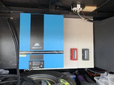
Hello there. I've tried to read as much as I can about 48v systems and 50 amp RV's but I'm not entirely sure how to get myself out of this bind, or at least the easiest. I had planned to put a SP6548 from SunGoldPower in with front storage along with 3 of their 100Ah server rack batteries. Everything was going well until I learned that 50 amp is 120 volt 180 degrees out showing as 240 volt. Didn't know that. I'm moving into this RV full time at the end of this month and everything is already set. I do not have any solar installed yet, this is just to be preemptive and be able to run things longer without the generator.

My options seem to be:

A) TRY to return the SP6548 and get a TP6048 which is the 120/240 split phase. Downsides is overall less solar input possible, and it weighs 73lbs, also the SP6548 got a little scratch on the top of the casing when I was trying to put an m10 bolt through a tight area so I'm not sure they will even take it back. I could end up shipping it in just to find out they won't take it.

B) Just route one leg to the inverter and then split that single leg into two wires going to the two main AC breakers? Then maybe just purchase a second one of the sp6548 since I was eventually going to try to take it all off the RV and put it on a house eventually. Downside is expense, I don't know how well this would really work, and somewhere I'd have to terminate a hot leg. And weight but only marginally more weight than the 73 lbs TP6048.

C) Not sure if this one works at all but maybe? Route one leg to one side of the circuit breaker straight off of the surge protecter (as it already is), and then route the other leg through the inverter and back to the other side of the circuit breaker? This screws me up thinking about Neutral though (learned on helicopters and DC mainly)

Stinks too because I didn't figure out this problem until after I already figure out how to install it in.

Any help much appreciated. Sorry if things are redundant, I really did try to read a lot of these threads about similar issues but neutral always is where I get stumped.
DE2E7613-A189-41EF-A315-492DB69972B2.jpeg
 
I went through the same, started with 1x 6548, and stepped up to 2x later on. The build thread might help you;

 
Thank you. This is helpful when I have time to go through all of it but only a portion is relevant to me and my build and my questions and its going to take a very long time to siphon through all of it. I need to make a decision very quickly about what I'm doing with this and I would like input on the options I presented and if they are even possible and the potential problems I might fall into going down that route. As far as a transfer switch, I did not plan a transfer switch as I was just going to power the entire coach through the inverter, if I went that route then would I wire the transfer switch in just before the circuit breaker panel and just run both inputs, one straight from the surge protector, one from the inverter into it?
 
If you need split phase 240vAC (L1 and L2 being hot and 180 degrees out of phase.) than you present AIO will not work for you. If you don't intend to run anything that requires 240vAC (just 120vAC) you can jumper RV L1 and L2 on the output. Be aware that you can not then connect to a 240vAC shore power. Once you add another AIO that allows stacking it can be set to do 240vAC split phase and the output jumper removed.

Various wiring strategies can be employed as well as transfer switches.
 
Thank you Mattb4. If I were to only only run L1 to the AIO, and let L2 just stop at the surge protector, I should still be able to plug into 240 correct? I would just only be getting the 50 amp on the L1 and limited to half of the service correct? That way I could connect to 30 amp or 50 amp and it would at least run, just at a degraded level?
 
Unless I am misunderstanding you the answer is no you can not have one hot leg powered by shore power 240vAC and the other hot leg powered by your AIO. They are not going to be in synch (except when running in AC Bypass) if you attempt to run a 240vAC item in your RV.
 
There is no real 240. Its 120 split 180 degrees out. So if you measure across them they will show 240. I have zero 240 volt appliances. I also do not have 3 A/C's Lt.Dan, just 2. So I understand I cannot combine the two hot legs or anything like that.

I had 2 questions, could I run L1 hot leg straight to one side of the circuit breaker panel (only 120v) and then run the other hot leg (still 120v just 180 out) through the inverter and then back to the other side of the circuit breaker panel?

The second question was, assuming I cannot do the above, can I just not run one of the hot legs at all and only run 1 through the inverter and then jumper at the AC OUT of the AIO to both sides of the circuit breaker panel.
 
You will need to rewire your RV shore power. It must run from the shore power plug into the AIO on the "AC in" side. If you are using a 240vAC input plug from shore power it will only connect 1 hot leg, neutral and ground at the AIO. The other hot leg must be dead ended and insulated. From the AIO's "AC out" terminals you will wire to your RV's CB panel. At the RV's CB panel you can power the two legs by jumpering L1 to L2. One way to accomplish this would by using a unused 240vAC breaker and wiring the output terminals together.

The AIO would than handle transfer from utility or inverter to AC out. it would provide 120vAC at what ever it is rated to do so and whatever shore power 120vAC can provide.
 
Great thank you. Thats exactly what I thought. Fortunately I have a full RV surge protector wired into the main line in so I have a convenient place for the L2 leg to be dead ended without having a hot wire just hanging loose. I'll just run 3 lines of the 6/4 cable off the surge protector to the inverter.

But just for my own knowledge and learning here. I want to explore why the other way that I presented would not work. I get stumped when it comes to neutral and all of this and I really want to learn more.

So the incoming 6/3 w/g comes in off of the plug and goes into my full RV surge protector, which then runs 6/3 w/g to the circuit breaker panel which splits L1 and L2 into 2 different sides of the RV.

What would happen if I instead ran 2 cables off of the surge protector the first one carries L1, Ground, and Neutral to the first AC circuit on the CB, and the other one carries L2, ground and neutral to the inverter and then out of the inverter back to the second AC circuit on the CB?

I'm not going to do this, I'm just trying to figure out where the problem or danger lies in this configuration and why.
 
The problem comes in that the AIO output when operating as an inverter is not synched to shore power. If you were running two AIOs with communication they would match their sine waves output so that they were a proper 180 degrees apart. Obviously between shore power and you AIO that can not be done.

Regarding neutral and ground. In the resource section thanks to FilterGuy is an excellent coverage of all aspects starting with Household and ending with RV/mobile. I linked the first below from which you can find the other pages.


Last edited:
Great thank you. Thats exactly what I thought. Fortunately I have a full RV surge protector wired into the main line in so I have a convenient place for the L2 leg to be dead ended without having a hot wire just hanging loose. I'll just run 3 lines of the 6/4 cable off the surge protector to the inverter.

But just for my own knowledge and learning here. I want to explore why the other way that I presented would not work. I get stumped when it comes to neutral and all of this and I really want to learn more.

So the incoming 6/3 w/g comes in off of the plug and goes into my full RV surge protector, which then runs 6/3 w/g to the circuit breaker panel which splits L1 and L2 into 2 different sides of the RV.

What would happen if I instead ran 2 cables off of the surge protector the first one carries L1, Ground, and Neutral to the first AC circuit on the CB, and the other one carries L2, ground and neutral to the inverter and then out of the inverter back to the second AC circuit on the CB?

I'm not going to do this, I'm just trying to figure out where the problem or danger lies in this configuration and why.
Sounds like it would work.

Draw a diagram just so I'm sure that I understand.

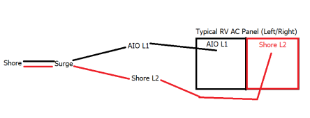
Diagram below...assuming nothing in your RV requires 240v, and that your AIO is 120v.
Side note...run 6/3+Ground to your AIO from your Surge and from your AIO to your RV AC Panel...leaves room for when you add a 2nd inverter.
1689027223489.png
 
Last edited:
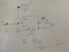
Apologies about how rough this is. Just sketched it down today. Something I had thought about at the same time as this is the limitation before getting a second inverter on not being able to use full 50 amp service. So I thought about what if I added a transfer switch that the shore power and the inverter power both tied into right before the circuit breaker panel. So this sketch kinda demonstrates that.

IMG_0654.jpeg

The idea here is that I can still use full 50 amp and charge my batteries with 50 amp, and then in all other cases (30 amp, 15 amp, generator, solar only) everything can just run off of the the jumpered connection from the inverter instead. This should keep both power supplies completely isolated so that I never get the 240 mixed into the in sync polarity off of the inverter.
 
Looks like it would work. Make sure you keep track of where the neutral comes from.
 
Looks like it would work. Make sure you keep track of where the neutral comes from.
Right, thats been the main thing I've been trying to think of because Neutral throws me off. But the way that I see this, if I'm on 50 amp and the transfer switch is in the position of using the 50 amp, then the sine wave and electrical charge that WOULD be dangerous to the system coming from the inverter is isolated by the transfer switch and doesn't touch anything sharing the 240 and the neutral of the 240. The only thing that would be would be the AC IN of the inverter where L1 only, neutral and ground would go, but the polarity would be correct there.

Having that load, in front of the transfer switch and circuit breaker, and only using L1 for battery charging wouldn't be a problem with the neutral would it? It would all still be apart of the same polarity as what is being fed into the rest of the system so I wouldn't think so.

Then in the other position, the entire main circuit breaker would be electrically connected back through the inverter, and so that would all just be 1 shared circuit with the only odd thing being that L1 and L2 share polarity meaning that neutral would have higher than usual current because the polarity is in sync rather than 180 out?

(Side question, does the inverter always change the polarity even if its using "passthrough"?)

Cannot seem to find a lot of these switches but I think what I'm looking for is just a 4p 220v? Or 110/220? Not sure if the switch is going to detect the synced polarity and kick off the "backup" power. This is the closest thing I've found so far...
https://www.amazon.com/Automatic-Tr...45&sprefix=220v+4p+single+thro,aps,130&sr=8-1
 
Last edited:
Back
Top