diy solar

diy solar

hwy17's Orion battery build

IMHO, get a torque wrench. You have too much invested to leave out this comparatively inexpensive tool.
I have an inch pound torque wrench but I also have an ingrained superstition from working on dirtbikes not to put a torque wrench on a 10mm bolt head. I have snapped bolts that way and never snapped one by feel. I will consider giving this bus bar a check and snug though if it's consistently higher resistance.
 
A check of the 1-2-3-4 cell connections and slight snug on 2 of them that would take it resulted in no IR changes as far as I can tell.

This may just be the reality of buying unmatched DIY market cells.
 
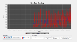
Charger kicked on. They say a battery is only either charging or discharging, but they switch back and forth between the two very fast.
Capture.PNG
 
Charger kicked on. They say a battery is only either charging or discharging, but they switch back and forth between the two very fast.

Yes, i saw mine was doing something similar just this morning. I was alarmed until i saw it was +10A to - 5A

I think its like making sausage (i grew up on a dairy farm in wisconsin), you really don't want to know what is really done. It would be GREAT and also EASY to do this better but there is no effort in making this better (as easy as it would be).

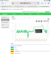
On my pic, the spike graphic is horrific while we slept and only the fridge cycled. At 6:30 the hot tub (1hp 120V pool pump) was turned on. Gas heat.

I dunno. Hopefully helpful/comforting. Seems like it should be smoother and more reactive.

I bumped my charge % up to 50% at 2:30, thus the spike. Was looking to get a little more charge and watch my suspect cell.


1709086749462.png
 
My utility room is being gently warmed by the double conversion inefficiency. Maybe about 300w. Nice for me in the winter because my toolbox and sort of work bench is in there too. Normally unheated.

The 2300W is very closely matched to our average consumption. The charger started at 50% SOC at around noon, and 8pm it's at 59% now.
 
Last edited:
Hot tub. I added an external pump, filter and natural gas heater in a little (3ft cube) sound-proofed out building. As much as i love a gas fired hot tub, i miss the days of cheap NG.
Hey it's still cheap compared to electricity, but maybe not solar.

I have a 160sq ft solar pool heater on my 18ft agp. It works well June-Aug, but not outside of that.
 
I ran the battery down to 0 SOC today and I think it was successful. Under 3kW load, cells first started dipping below 3V at 2.5% SOC and we're all still in the 2.9's at 0% SOC. I don't know if this really constitutes a reliable capacity test, but I'm just glad that it's not overestimating capacity and crapping out at 20%.

I did notice that during particularly hard pull of about 100-120 amps at 20ish SOC live voltages did get erratic with spikes down to 2.5V. I need to read the voltage control logic in Orion better to understand exactly when it's going to react to an overdischarge.
 
My double conversion trial ended yesterday after I went to investigate auto charger output not applying and when I poked at the wiring harness in the orion, the charge contactor would open. The controls harness is a much smaller connector than the cell tap harness, and I wish they would use something more sturdy. I can't tell how it was lose, but I reseated it and I can poke it now without issue, and auto charger works fine.

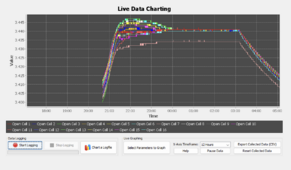
This is the first rebalance. It's not under load so balancing will probably not stay this tidy once it is. But it seems fast enough to me, idk.

Screenshot 2024-02-29 at 5.05.24 AM.png
 
Last edited:
5-6mV difference at 3.40+ correlates well with top balance.
It would be extra satisfying to whip cell 7 into perfect alignment, but I know we're actually just looking at this super zoomed in. If it could be zoomed out, it would look like full consolidation. And, when it's doing this under load .007 is already going to be a tight target.

Cell 7 was low in the initial balance too, so I think it may just be it's original state of charge still showing through, and not a problem with the cell.

Given the scale of the deviations, you are picking fly turds out of pepper... :p

"perfect" is often hard to attain. If you stay < 50mV @ peak absorption, you've won.
 
Reseating and tightening the bus bars on cell 3 did solve the high resistance numbers I was seeing for that cell.

Now it's actually got a lower resistance than every other cell. I'll tighten the other now highest ones, but try not to get carried away until I snap a stud.
 
The Orion comes with a big sticker on it that says DON'T RECONFIGURE BUS BARS WITH WIRING HARNESS CONNNECTED.

In the manual, every other page says DON'T RECONFIGURE BUS BARS WITH WIRING HARNESS CONNNECTED.

In the software, it gives you pop up warnings: DON'T RECONFIGURE BUS BARS WITH WIRING HARNESS CONNNECTED.

So what do I do when I go to reseat bus bars on 3? Forget to disconnect the wiring harness of course.

I got away with it this time, I hadn't fully lifted the cell tap by the time I noticed. It's just too easy a mistake to make. Would be best to have a physical interlock that prevented me opening the cell box without disconnecting the harness first.
 
2300 watt grid input turns out to be inadequate. It can serve our 24 hour average requirements if the system is set to an 80% charge target but it's not enough to be able to timer off the grid during 4-9pm and then recover all the 24h consumption in the 19 hours of on time.

Also, once the solar gets up I'll want the charger to hold the battery at 20% to leave room for solar storage, so then I'll need peak output input to reliably backstop that.

Gonna probably get another 2300 watt.
 
Greetings,
I am very familiar with Orion BMS2. Not the junior. There must be a HW difference as the junior appears to measure in groups of 8 and not 12 like most BMS chipsets. Sofware looks the same.

The drift points are just to force the SOC reading to show whatever you want. I would keep the default for your cells.
True DeltaV is better checked at high SOC. less than 90% can make DeltaV look better than it is.

DeltaR is not good. Dielectric grease between busbars is a good idea. If DeltaR stays high I would swap out the cell. The sense wire resistance does not affect this.

The resistance chart needs to be populated with the correct cell resistances. Will prevent CCL & DCL from being reduced.

The Orion only balances the individual cells at a fraction of an Amp. <0.5 I think. fine with 20Ahr, will take days with 200Ahr.
I would only balance if a cell is above 3.5 with a max of 3.65. The fastest way to balance with Orion is to set the charging current at an Amp or less.

Cheers,
Iain.

PS, Cell #10 is the weak link.
Hey! Thank you for reading.

As I understand it the Jr uses 2 of the the same 12 point IC's, with the last 6 disabled or closed. And I believe the Jr1 did so in a 12/4 split, so the even 8/8 split was an improvement for the Jr2 to allow pack splitting fuses like mine.

CCL/DCL are not a feature I consider myself to be utilizing yet, because I have no loads or chargers that can receive a DCL/CCL comm and react to it. I have the pack fused at 150 and I have my DCL/CCL set to allow 150+ with spikes to 300 under almost all circumstances. I'm not sure if I will ever tighten that down.

For now I plan to only charge to 3.437 at all stages from all charge sources, and only balance at 3.438+. I've considered charging to 3.437 and balancing at 3.44 to really ease back on the balancing activity and I might try that later.

I'm gonna try tightening the bus bars on 10 next to see if that resistance goes away.
 
Hi,
I was able to use CCL/DCL over Can. Shame you cannot.
it's a good idea to set DCL/CCL so you can set conditions for the contractors to open under fault conditions. I see you have set this.
I would initially charge to 3.65v so that DeltaV was more informative.
I would relocate the weakest of the cells to the end of the string & have the end of the string easiest to get to for cell replacement.
I do like the Orion BMS SW.

I wonder if I can paste a profile? Nope. LOL.

Cheers,
Iain.
Yeah I have some canbus messages that I might be able to get to shutdown my inverter, but otherwise the only option and the only currently enabled option is for contactors to open. I'm relying on my high DCL and CCL only to open the contactors in an extreme fault scenario, if the 150 amp fuse has somehow not already blown.

Contactors also react to high and low cell voltages of course. Also expecting those to never have to open in normal operating conditions.

I'm gonna keep working with 3.437 to try it out, it's kind of my pet project to trial single voltage charging in home storage applications - absorb and float and balance at 55v even.

I probably won't be re arranging since my case is so hard to work in. Luckily 10 is already in a more accessible position.

Do you have any advice on finding resistance factors for the EVE 304's? I'm a bit lost on that, and just relying on my uncalibrated figures as a delta indicator to point out the odd cells, like 10.

Have you ever looked at Nuvation or FoxBMS? I think I will try Nuvation on my next build. They are a north american commercialized version of FoxBMS.
 
Back
Top