You are using an out of date browser. It may not display this or other websites correctly.
You should upgrade or use an alternative browser.
You should upgrade or use an alternative browser.
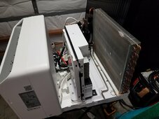
Midea U 12k power from DC (IT WORKS!!!)
- Thread starter AntronX
- Start date
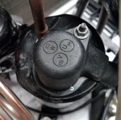
Everything appears to work with the unit except you never hear the compressor kick on and therefore never get any cold air. How and/or where do I measure the compressor resistance? And if there is a short then what?Measure compressor winding resistance to look for shorts. If comp is OK then check internal fuse on controller board. Edit: If display lights up then main fuse is OK.
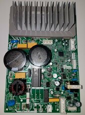
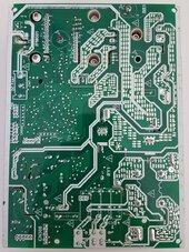
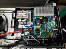
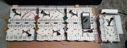
Looks like this board can be powered with 340Vdc since everything appears to get power from -170v and +170v points and nothing is connected to center tap. I traced power paths for compressor and fan inverters, logic psu and indoor fan motor supply. Everything runs on 340Vdc. I just need to make sure series capacitors stay balanced and not become overvolted. Maybe small load resistor on each cap will keep them in balance.
BradCagle
Solar Enthusiast
- Joined
- Aug 27, 2021
- Messages
- 577
Looks like this board can be powered with 340Vdc since everything appears to get power from -170v and +170v points and nothing is connected to center tap. I traced power paths for compressor and fan inverters, logic psu and indoor fan motor supply. Everything runs on 340Vdc. I just need to make sure series capacitors stay balanced and not become overvolted. Maybe small load resistor on each cap will keep them in balance.
Interesting.
So it may not care what the AC frequency is. Wonder if you could use one of these simple HF converters?
It's 20khz instead of 60hz, but if all the air conditioner unit is doing is rectifying then seems it might work.
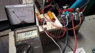
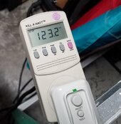
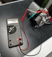
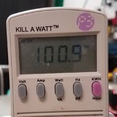
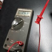
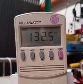
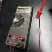
Powered it back up from AC power. At 120vac DC voltage was 333v with only 11w fan load. With compressor on low speed around 260Wac DC dropped to 303v. Power factor was 0.7 It ran without change down to 100Vac and 250Vdc. At around 220Vdc condenser fan motor spun up fast but compressor speed remained same. Increasing voltage also increased condenser fan speed until it settled back down to slow speed at 250Vdc. In fan only mode I increased input voltage to 132Vac which produced 361Vdc on the caps. No errors reported. So it seems that usable DC voltage range is at least 250 - 360Vdc. I did not go further than this range to play it safe for now. I guess DC powered test is next.


Last edited:
Consumerbot3418
Fitting square pegs into round holes... for fun?
I've got one of these units sitting on a shelf--seems to have leaked its refrigerant, as it gradually did a worse and worse job of cooling. Happened under warranty, so I got a refund from Midea. Kinda glad, cause my inverter hated it! Horrible LED flicker that was eventually traced to this thing.
@AntronX , If you need another board for whatever reason, let me know. I was planning to scrap this unit, after salvaging the motor, transformer, heat sink, caps, etc.
@AntronX , If you need another board for whatever reason, let me know. I was planning to scrap this unit, after salvaging the motor, transformer, heat sink, caps, etc.
Sure, Thanks! I will take that board and other parts you may have. I may want that compressor as well.@AntronX , If you need another board for whatever reason, let me know. I was planning to scrap this unit, after salvaging the motor, transformer, heat sink, caps, etc.
RCinFLA
Solar Wizard
- Joined
- Jun 21, 2020
- Messages
- 3,565
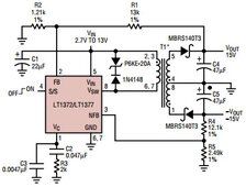
I don't think you will ever find an active power factor correction on a 120vac variable speed inverter A/C. With the low frequency 3 mH choke the power factor will be 0.80 to 0.85 range varying with compressor speed load. The low freq filter inductor is necessary to avoid randomly popping a 120vac branch 15 amp breaker on peak current with a 12-14kbtu unit.
The voltage on output of choke and on the filter capacitors will be about 165vdc peak with about 10-20v of 120 Hz ripple voltage depending on compressor speed loading.
There may be some other smaller power supplies that require 120vac input to run relays, reversing valve, and thermostat.
The voltage on output of choke and on the filter capacitors will be about 165vdc peak with about 10-20v of 120 Hz ripple voltage depending on compressor speed loading.
There may be some other smaller power supplies that require 120vac input to run relays, reversing valve, and thermostat.
Nope, it all runs on 340Vdc internally. Unless I missed something then I will find it where the smoke comes out.There may be some other smaller power supplies that require 120vac input to run relays, reversing valve, and thermostat.
Last edited:
On slowest speed total power consumption is 316V * 0.34A = 107 watts. Outlet air temp is 57F and intake is 72F. With 95% efficient 12v to 316V dc-dc converter you could run it on 12V LFP battery with only 9 amps. Perfect for vans or camping.
RCinFLA
Solar Wizard
- Joined
- Jun 21, 2020
- Messages
- 3,565
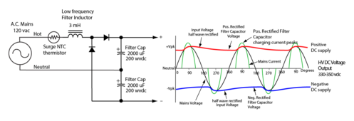
Was just drawing that up. Actually, it is two half wave rectifiers to produce twice the voltage.
Be careful because each DC supply terminal will have voltage to ground bonded AC neutral.
The whole inverter/compressor is floating, other than metal case ground.
They are likely doing this so they can use the same compressor and inverter as 230vac European mini-splits.
You likely draw about 10 amps from 120vac at full speed with a power factor about 0.8, but it is peak current crest factor that hurts.
The surge resistor likely has a bypass relay once caps are initially charged. 2000 uF without surge limiting would blow breaker every time and saturate the inductor likely magnetically biasing the filter inductor core from the large surge current.
Once it is plugged in to 120vac outlet the HVDC likely stays live whether unit is running or not.

Last edited:
I think so too. Beautiful drawing you made. What software it that?They are likely doing this so they can use the same compressor and inverter as 230vac European mini-splits.
RCinFLA
Solar Wizard
- Joined
- Jun 21, 2020
- Messages
- 3,565
Adobe Illustrator.I think so too. Beautiful drawing you made. What software it that?
RCinFLA
Solar Wizard
- Joined
- Jun 21, 2020
- Messages
- 3,565
You could run two 165 vdc batteries with common neutral-ground connections of opposite 165 vdc battery polarities. A slight bit safer as you only have to worry about touching one lead of each battery.
About as dangerous as a high voltage PV array.
About as dangerous as a high voltage PV array.
Similar threads
- Replies
- 10
- Views
- 989
- Replies
- 5
- Views
- 2K
- Replies
- 21
- Views
- 2K
- Replies
- 140
- Views
- 15K


