I am thinking to leave both positive and negative floating in reference to ground and use isolation monitor instead. This way if I come in contact with one wire I will not feel any shock but isolation monitor should pick it up and shutoff power.
You are using an out of date browser. It may not display this or other websites correctly.
You should upgrade or use an alternative browser.
You should upgrade or use an alternative browser.
Midea U 12k power from DC (IT WORKS!!!)
- Thread starter AntronX
- Start date
That's what I observed in my test from day before. DC caps stay live as long as 120Vac is present.Once it is plugged in to 120vac outlet the HVDC likely stays live whether unit is running or not.
zanydroid
Solar Wizard
There is a 350V rail inside any 240V AIO. Does that count?Nice work ! Are there practical 12V or 24V to 280V boost converters? Hmm I'd love to run my 230VAC mini split on direct 24V DC someday
Thanks! Not that I am aware of anything practical. There are dc-dc boost modules on aliexpress but definitely not something plug and play.Nice work ! Are there practical 12V or 24V to 280V boost converters?
As long as it stays below 360V i guess you could tap hvdc bus from one of those inverters. But some of them like the Growatt 5000es have 450v bus that may be too high for this air conditioner.There is a 350V rail inside any 240V AIO. Does that count?
zanydroid
Solar Wizard
Got it. Well if someone is going to do this surgery they should test first and ask aroundAs long as it stays below 360V i guess you could tap hvdc bus from one of those inverters. But some of them like the Growatt 5000es have 450v bus that may be too high for this air conditioner.
I’m not sure if there is value to tapping HVDC vs using the inverter output. My idea was: what is the most basic bitch, mass market device with such a boost converter of this size.
Maybe if one can turn off the AC load search and save some power. Also maybe the boost converter reacts better to load changes than boost + inverter.
Tapping dc bus allows for slightly higher efficiency and avoiding issues like flickering lights. A suitable AIO unit will have to be tested and potentially firmware modified. But my goal is 350Vdc loads in the house like inverter based air conditioners, instant water heaters coupled directly to 350Vdc battery which is powered by high voltage DC rooftop solar strings. For cooking I think I can use 240Vac powered induction cook tops that must be also rectifying 240Vac up to 340 - 400Vdc. This way most high power loads in the house are kept on hvdc avoiding the need for big and expensive 48v to 120/240v inverters. And added benefit is redundancy since there is no inverter.I’m not sure if there is value to tapping HVDC vs using the inverter output.
zanydroid
Solar Wizard
One thing I’d love to know from this is how it affects the noise signature from the induction.For cooking I think I can use 240Vac powered induction cook tops that must be also rectifying 240Vac up to 340 - 400Vdc.
I believe you get kHz multiplied with 60hz or 120hz by default (I don’t think they do any smoothing)
But with DC in you would only have the kHz component.
So would it sound better?
(I’ve resigned myself to buzzing on induction).
It would be silent if PWM frequency is above human hearing upper frequency limit. But I never tried induction cooktop before. I may get one of those table top single burner units to experiment with.So would it sound better?
zanydroid
Solar Wizard
It would be silent if PWM frequency is above human hearing upper frequency limit. But I never tried induction cooktop before. I may get one of those table top single burner units to experiment with.
Until I realized that the kHz frequency was layered on 120Hz I was confused by how noisy they were and how much energy I could hear.
Wikipedia says 25-50kHz as the operating frequency of induction burners so it is possible it will be silent.
Actually there are a lot of people I know in the cooking world that are triggered by the harmonics starting at 120Hz, and I had previously decided that they were SOL. But maybe induction cooktops should just include a few 3kW boost converters inside. The SMPS frequency should be much higher than 120Hz and also easier to manage than some buzzing induced inside the pans.
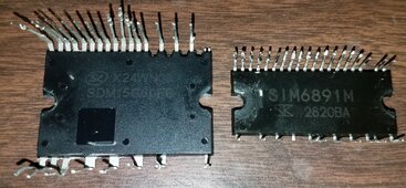
Thanks to @Consumerbot3418 for sending me inverter board and parts from same model Midea AC unit. I was able to de-solder power modules to get part numbers. They are SIM6891M 600V 2.5A (400V DC max input rated) and SDM15G60FB 600V 15A IPM modules. Both should be OK to operate from 96 cell Li-ion EV battery pack.

Last edited:
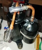
Thanks again to @Consumerbot3418 for sending me compressor as well. Now I have a spare or something to experiment with. I got it to spin using RC brushless speed controller powered from 60Vdc. Just enough to unstick the valve to let argon/co2 welding gas to flow through it to hopefully purge any trapped moisture from the air. Capped off the tubes and off to storage it goes for now. Hopefully doing this will prevent POE oil from going acidic and doing damage. I will probably replace it with fresh oil. Just have to figure out how to drain old oil and how much new oil to add.

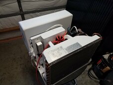
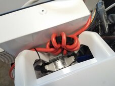
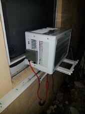
This project is coming to an end (for now). Weather is getting hot so I need it back in service. Installed junction box outside to route AC and DC power through. It's nice not having indoor power cord. Looks neater that way. Wrapped 8 turns of DC cable through FT240-31 toroid for EMI/RFI reduction. 3rd pic shows a hole and dam to keep condensate from reaching bottom of condenser and fan. Surprised this thing still cools after all the abuse.


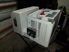
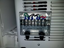
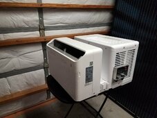
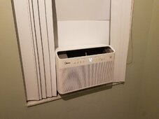


Vigo
Solar Addict
Dunno how i missed this the whole time. I missed my chance to contribute anything since i had opened one of mine last year and identified the voltage doubler circuit and thus the rough operating voltage etc, but a lot of the rest of this is over my head.
Mine has been sitting dormant since i installed a mini split in my room, but i intend to convert the Midea to a split unit and put it in a conversion van. Time will tell if i follow through. Thanks for posting all of this.
Mine has been sitting dormant since i installed a mini split in my room, but i intend to convert the Midea to a split unit and put it in a conversion van. Time will tell if i follow through. Thanks for posting all of this.
This forum is getting so big that some threads get lost in the torrent of new posts. Not a bad thing but does result in some interesting threads getting pushed down quickly. I usually browse by what's new.Dunno how i missed this the whole time.
My next goal in this project is to install DC modded mini split. Will have this Midea run for another summer. It accomplished its main task of proving that inverter ACs can run on DC. That was the major reason I bought it to replace perfectly fine 5k BTU single speed box.Mine has been sitting dormant since i installed a mini split in my room
Vigo
Solar Addict
As far as i know, anything that has a rectifier section and actually runs on DC, you could put DC straight through the AC cord and it would function, you would just be eating some pointless diode losses from passing through the rectifier section. But your way is nicer!
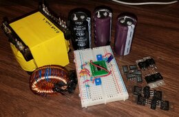
Parts harvested from dead Aims 1500W 48V inverter that will become DC-DC converter for Midea aircon. E55-N2Z0Q 48V/120V 4:17 ferrite transformer good for 3kW surge. Measured 90nH primary leakage inductance with secondary windings shorted. Full bridge driver and rectifier circuit. SG3525 PWM controller (on breadboard) originally set to 36kHz. I will experiment with different PWM frequencies. VO3120 opto isolated 2.5A gate driver ICs harvested from scrapped UPS. MUR3060 fast rectifier diodes 0.73Vf at 1A. And 70N10F4 100V 60A 15mOhm MOSFETS I had laying around (6 of 8 original IRF8010 fets got fried). Will use 50V 1000uF Rubycon ZLH low ESR caps (not pictured). Kinda close to rated voltage but my batteries never go above 48V (4V/cell, 12S Li-Ion).

Last edited:
toddincabo
New Member
Excellent work, I'm going to be installing this exact model into my RV and would love to have the choice of AC or DC. Do you use a switch to choose between the two before powering on or does it not back feed in any way? Have you tested DC draw and amps with a "kilowatt" meter during use on a really hot day yet? Also, could you please give an estimate of the efficiency difference between the two using this mod or just AC plugged in? Thank you.Installed junction box outside to route AC and DC power through.
No switch yet, still running on AC from 800 watt inverter. Worst case power draw (from grid) was 1200W on hot day and high setting. At low and medium setting there is not a noticeable efficiency difference. Main difference will come from using ~96% efficient DC-DC converter vs. 84% efficient inverter.
Similar threads
- Replies
- 10
- Views
- 992
- Replies
- 5
- Views
- 2K
- Replies
- 21
- Views
- 2K
- Replies
- 140
- Views
- 15K


