Does this UNUSUAL way of connecting the storage battery modules with the DEYE inverter (we assume here that the modules will be wall-mounted and not one on top of the other) seem correct?:

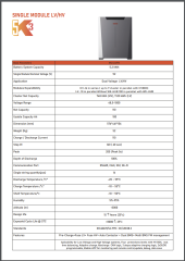
This is the method proposed by the company's technical person who deals with the sale of these storages from the scheme (two-voltage Weco 5k3 XP - 5.3kWh, 5.2kW power, charging / discharging current 100A / 150A for 30s and peak charging current 200A for 5s, 7000 cycles, possibility of discharging up to 100%, each has its own BMS, built-in protection [FUSE])...
Interestingly, my father (electrical education) AND a PV installer (with experience only in high-voltage warehouses) AND a car electromechanic AND a consultant on the DEYE service hotline initially admitted that from the electrical side it looks OK - i.e. these modules are still connected in parallel - BUT it's done on the contacts in the inverter...
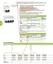
For me as a layman without electrical education, this proposal also makes sense - we have thinner 25mm2 wires here (in which no current greater than 100A should flow - DEYE SERVICE says that the inverter will give a maximum of 210A, but this current will be divided in the inverter's contacts into 3 such wires 25mm2), EACH battery module is protected by an overcurrent circuit breaker Schneider C120N-C100-1 C 100A, the card of which shows that it has the appropriate parameters for DC current (electician was surprised that there would be protection used for AC - but it turns out that it is also designed for DC).
I tried to consult this diagram on the Italian WECO support, but the replying person was probably annoyed that I was interrupting his siesta because he first replied "You must connect all the batteries in parallel and after connected to the inverter" (as if he did not understand that there is a connection in the diagram parallel) and then when I was digging into the topic, he cut off the conversation like this: "Please follow as our user manual says for warranty of the product. We advise all the possibilities of the system installation"")
I also consulted it on FB groups related to LiFePo4, but no one responded.
I also consulted this with an experienced installer from the FB group regarding PV and he wrote to me that it could not be so - but when I asked for details, he only "recommend reading reversing currents of photovoltaics". Perhaps this is some argument that would exclude the use of such a method (if something like this can occur here) - but probably I lacked the knowledge to understand the materials I read ;[
An alternative to the above method would be to make the connection strictly according to the WECO instructions:

Well, but this way means that there will be a lot of this 50mm2 cable (together 12.5 m...). As you can see here I put a 250A DC protection, which I managed to notice on YT videos from some fairs - and that's how I found it at https://www.beny.com/product-item/bess-dc-breaker-bdm-series/
Interestingly, the MCCB BENY 250A turned out that in the DEYE instruction on the diagram of connecting the storage to the SUN-10K-SG04LP3-EU, they incorrectly show that you need 300A DC protection - some technical representative claimed that "this is a mistake", that "due to gradation, 250A can be used", and that "the inverter has its built-in 300A DC protection"...
The gentleman also said that we cannot use our connection method ("C") from the first diagram (although unfortunately we did not ask why) and suggested that we use another connection method, using self-prepared rails-flats, in which we would have to connect everything:

This version has an advantage over the version marked "A" - i.e. instead of over 12m of thick cable, about 3 meters is enough, and for this you can use 25mm2 cables, which in Weco are included in the mounting kit in wall mode ... But it is quite a lot of connections, everything takes a lot more space - generally it's more complicated...
There would probably be no doubt at all if the modules were mounted on top of each other - then short factory BUSbars would be used, 2x50mm2 to the plus, 2x50mm2 to the minus. However, due to the lack of space, the plan to use wall mounting was created with this proposal with 3x 100A DC protections, which some of the "technical group" do not accept as correct My father even wondered aloud about the conspiracy theory, according to which the solution with thick double 50mm2 wires / expensive protections 250A DC is imposed by "Business" - why sell 3x100A (3x32 EUR) with 25mm2 cables when you can sell 1x250A (225 EUR) with expensive 50mm2 cables
I would like to ask if this "C" solution (protection 3x100A DC) cannot actually be used?
This is the method proposed by the company's technical person who deals with the sale of these storages from the scheme (two-voltage Weco 5k3 XP - 5.3kWh, 5.2kW power, charging / discharging current 100A / 150A for 30s and peak charging current 200A for 5s, 7000 cycles, possibility of discharging up to 100%, each has its own BMS, built-in protection [FUSE])...
Interestingly, my father (electrical education) AND a PV installer (with experience only in high-voltage warehouses) AND a car electromechanic AND a consultant on the DEYE service hotline initially admitted that from the electrical side it looks OK - i.e. these modules are still connected in parallel - BUT it's done on the contacts in the inverter...
For me as a layman without electrical education, this proposal also makes sense - we have thinner 25mm2 wires here (in which no current greater than 100A should flow - DEYE SERVICE says that the inverter will give a maximum of 210A, but this current will be divided in the inverter's contacts into 3 such wires 25mm2), EACH battery module is protected by an overcurrent circuit breaker Schneider C120N-C100-1 C 100A, the card of which shows that it has the appropriate parameters for DC current (electician was surprised that there would be protection used for AC - but it turns out that it is also designed for DC).
I tried to consult this diagram on the Italian WECO support, but the replying person was probably annoyed that I was interrupting his siesta because he first replied "You must connect all the batteries in parallel and after connected to the inverter" (as if he did not understand that there is a connection in the diagram parallel) and then when I was digging into the topic, he cut off the conversation like this: "Please follow as our user manual says for warranty of the product. We advise all the possibilities of the system installation"
I also consulted it on FB groups related to LiFePo4, but no one responded.
I also consulted this with an experienced installer from the FB group regarding PV and he wrote to me that it could not be so - but when I asked for details, he only "recommend reading reversing currents of photovoltaics". Perhaps this is some argument that would exclude the use of such a method (if something like this can occur here) - but probably I lacked the knowledge to understand the materials I read ;[
An alternative to the above method would be to make the connection strictly according to the WECO instructions:
Well, but this way means that there will be a lot of this 50mm2 cable (together 12.5 m...). As you can see here I put a 250A DC protection, which I managed to notice on YT videos from some fairs - and that's how I found it at https://www.beny.com/product-item/bess-dc-breaker-bdm-series/
Interestingly, the MCCB BENY 250A turned out that in the DEYE instruction on the diagram of connecting the storage to the SUN-10K-SG04LP3-EU, they incorrectly show that you need 300A DC protection - some technical representative claimed that "this is a mistake", that "due to gradation, 250A can be used", and that "the inverter has its built-in 300A DC protection"...
The gentleman also said that we cannot use our connection method ("C") from the first diagram (although unfortunately we did not ask why) and suggested that we use another connection method, using self-prepared rails-flats, in which we would have to connect everything:
This version has an advantage over the version marked "A" - i.e. instead of over 12m of thick cable, about 3 meters is enough, and for this you can use 25mm2 cables, which in Weco are included in the mounting kit in wall mode ... But it is quite a lot of connections, everything takes a lot more space - generally it's more complicated...
There would probably be no doubt at all if the modules were mounted on top of each other - then short factory BUSbars would be used, 2x50mm2 to the plus, 2x50mm2 to the minus. However, due to the lack of space, the plan to use wall mounting was created with this proposal with 3x 100A DC protections, which some of the "technical group" do not accept as correct
My father even wondered aloud about the conspiracy theory, according to which the solution with thick double 50mm2 wires / expensive protections 250A DC is imposed by "Business" - why sell 3x100A (3x32 EUR) with 25mm2 cables when you can sell 1x250A (225 EUR) with expensive 50mm2 cables I would like to ask if this "C" solution (protection 3x100A DC) cannot actually be used?