diy solar

diy solar

Planning a Sol Ark 15k system for our ranch, after solar company went bust.

I think you mis-understood, im talking about getting 2 of the 4-1s because i cant find a 2-1s or 4-2s with everything plug and play and simple.

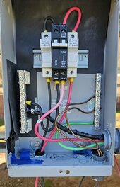
That would give me 8 total inputs, but i only intend to use 2 inputs on each one. And I know the fuses are built into the combiner, but some have 10A some are 15A, some are 20A, which one is right for this purpose if i use two of the 4-1s??

View attachment 209048
I suppose you could do that.

2 parallel strings would be 16 amps max.
 
Last edited:
all panels are identical, and yes i know the vinyl is cracking on them, here in arizona we are a very dry climate thankfully, but i also plan to go through and put sealer on them, they are used panels, i paid 20 bucks a piece, the faces have no spider webing, no de-lamination, no air pockets or bubbling like ive seen on others its just the vinyl backing.
View attachment 208983
I see a few major problems at work here.

First, it is very nice that you built a ground mount for your panels. Except every panel by a reputable manufacturer has a specification sheet and an installation sheet. These sheets detail exactly where the panel can be mounted to the rails in both the portrait or vertical position. If you don't follow those mounting positions, then the panel frames will not hold up for long due to lack of proper support. To me, it looks like the photos show the panels mounted near their edges leaving little to no support in the center of the panel.

Second, panels need to be grounded. The fact that you screwed in a bracket to the panel frame and the steel tubes is not acceptable evidence of proper grounding of the panels to earth. I suggest you obtain a UL listed grounding lug for PV panels and connect to each panel and then run your 8 or 6 awg bare copper wire in as close to a single run as you can to a grounding rod at the array. While the posts are in cement and cement is a ground conductor, it is not a substitute for a grounding rod.

Third and most important is that "cracks" you have shown in your photos on the back side of the panels. That material is not vinyl and cannot be repaired by just caulking over the cracks. The purpose of that material was to encapsulate the PV wafers and their buss bars and soldered connections to keep them free of any moisture and corrosion causing hot spots. Those cracks have allowed moisture in as well as broken the encapsulated seal. And there are a lot of them. The silicon wafers that are the cells produce about a 0.5 volt differential when the sun strikes them and then these cells are connected in series within a panel. It is extremely important that no water of even the smallest amount is present or there will be a short circuit in the panel itself and current may flow in the wrong directions as well as flow from PV+ to ground or can even be PV- to ground. The new inverters that are transformerless and have built in MPPT charge controllers also have a built in GFCI DC breaker. If any current exceeding say 0.5 amps goes from PV to ground, then the inverter gfci breaker will trip and the PV will be cut off. Then you will have to go panel by panel and do exhaustive testing to find the culprit and remove it or try a repair. What I am saying is you cannot reliably fix these panels even if they don't fault right away and that is why they were taken out of service.

I strongly suggest that you remove any panel that has cracks. If buying used panels, a very careful inspection is required besides testing with a panel multimeter and ground fault detector.

Forth, the comments about using each MPPT controller vs. running a string in parallel is simply wishful thinking. PV panels have been run in parallel strings for many, many years and there simply is no drawback to running strings in parallel. In fact, each MPPT controller on a Sol-Ark 15 has 2 parallel string input capacities for a total of 3x2 = 6 strings.
 
Forth, the comments about using each MPPT controller vs. running a string in parallel is simply wishful thinking. PV panels have been run in parallel strings for many, many years and there simply is no drawback to running strings in parallel. In fact, each MPPT controller on a Sol-Ark 15 has 2 parallel string input capacities for a total of 3x2 = 6 strings.
Who said any different ?
 
I noticed some of the hardware being recommended to you.

I have attached 2 photos of my iron. The first is how I wire my combiner box. The boxes I use are Midnite Solar MNPV-6. They are metal. But you can use any combiner box that is outdoor rated. Preferably UL listed too.
Looking at the photo, on the right side is the ground buss bar showing one green wire and other bare copper wires. This output the ground to the disconnect switch and to a grounding rod for the array and is connected to all panels and cross members by lay in lugs bonded to the metal frames. One the right is the PV- buss bar. It is insulated by stand offs from the metallic case of the combiner box. The PV- black wire comes from the array and to a solar fuse in a DIN rail mounted holder. The output from the fuse goes to the PV- of the high voltage double pole circuit breaker. The PV- exits the breaker to the PV- buss bar. The PV- goes out from this buss bar to the inverter. The lightening arrestor PV- is connected to this buss bar also as well as to the ground buss. The PV + comes from the array into the solar fuse DIN rail mounted solder. It exits this holder and goes to the PV+ side of the DC breaker which is a DPDT high voltage 15 amp breaker. The fuses are 20 amp. The PV+ exits the breaker and is connected across the DC disconnected switch which in this case is a triple pole single throw for 3 arrays. The switch is rated for 600 VDC and 30 amps. The exit from the switch then passes into the conduits the PV-, PV+ and a ground wire from the ground buss bar of the disconnect switch.

Hopefully this is helpful to you.
 

Attachments

  • 20240319_113229.jpg
    20240319_113229.jpg
    149.9 KB · Views: 9
  • 20240319_152554.jpg
    20240319_152554.jpg
    107.5 KB · Views: 8
just filling in some missing information, been sick today, thinking i got some bad food, so haven't gotten much of anything accomplished but i went out and inspected the main box more deeply.

Center double breaker says 200A on it, the breaker appears to be all one piece with one big arm, rather than 2 with a removable joiner on the arms, it appears to be the main shut off for the whole box, but it seems to also double as the feed to the house as well, as the cables that go to the house are connected to the bottom of it.

The Double breaker for the shop, which is the left one, says 100 on both halfs which are connected together.

The double breaker for the well system which is on the right, says 30 on both halfs that are connected.
 
So if I understand you correctly, you have 200 amp service coming in to the property. It seems that from this service entrance, there is a 100 amp feeder branch circuit (goes to shop sub-panel) to your shop and a 30 amp feeder circuit (no sub-panel here) to your well. The 200 amp mains then also travel to your home where there is a panel present. So the question becomes is the panel in the home a sub-panel or a main panel?
The main panel will be identified by having a neutral and ground connection where the utility service enters. This should be identified at the very first connection point where the 200 amps and meter are located. Once this is done, then the panel in the home is a sub-panel, not a main panel.

There is only 1 ground to neutral bond from utility to all supplied circuits on the property that are grid tied.

If this is correct, you can take the 200 amp service feed, connect it to an AC disconnect/bypass switch of 200 amp capacity. Take the 200 amp output from this switch to 2 places: The first back to its current location so everything is fed as it is now. The second into the grid tie of a Sol-Ark 15k. Then with panels and batteries hooked up, your Sol-Ark will serve as a whole home back up. The second option is to also connect the home sub-panel to the Sol-Ark using a second bypass switch between the Sol-Ark and the home panel. This way the home's panel is a "critical load" and always powered by the Sol-Ark while the well pump and shop would be powered by "selling back to the grid" function of the Sol-Ark when solar output and batteries have enough power output. The purpose of the second bypass switch between the Sol-Ark and the home subpanel is wired as a critical load is to supply utility power to the home when you shut down the Sol-Ark for servicing.

Your system is very doable. I am just worried about you trying to rely on used, unbranded PV panels that appear damaged. You can pick up new, high efficiency panels in the over 400 watt range for about $200 a piece right now. Save yourself headaches and think about this.
 
If I can get the system functioning, then i can monkey with replacing panels, etc, if they were sitting in a pile on the ground, maybe, but they are all already mounted up on the structure. I will be able to de-activate a set at the combiner box and even replace them as needed a section at a time in the future.
 
Getting ready for a business trip, but thought i would drop these items here so discussion can flow for when i get back, i was looking at using this as the panel the sol-ark would feed power to, and to make the house branch off from.

1713812048320.png
Why so big? because every damn breaker box on the property is completely full, because they bought the smallest boxes i have ever seen, and i am tired of that b*****it, if i need to add something I shouldn't need to share breakers or replace the entire breaker box.

1713812082119.png
to feed house and shop sub panels was the idea with these???? Shop is currently on a 100A from meter box.

1713812104991.png
Well Pump + Spare, had one breaker melt so figured having a spare on hand is good practice.

1713812127593.png
to add another 50 amp outlet Nema 14-50 for an RV, only occasional use, + spare.

1713812150747.png
These would mostly be for spares, some outdoors outlets i want to add around the shop and carport, and perhaps some exterior lighting which would all be LED.
 
sitting in the middle of the 4th power outage in 7 days, with this power company ED3 who couldn't find their own axes even though their heads are at full insertion, a large part of pinal county is down, because they didnt plan in any redundancy. mismanagement at its finest.
 
OK home depot order arrived, had some stuff come up, had to do some traveling on business.. Haven't got the new box even un-packaged yet, but also computed around in my head a little bit, and had some thoughts, i know, scary, but hear me out.

Right now if i chain up the panels in 4 rows of 12, that gives me 4 rows, each operating at 432 volts @ 240 watts. This puts me over the Sol Arks rated operating voltage limit by a nose...

Would it be better to instead chain them together in 8 sets of 6 panels and then parallel 2 sets each, which if my math is working today would be 4 parallel sets at 216 volts @ 480 watts. and then paralleling 2 of those togeather going into the sol arks MPPTs, should give me 2 sets of 216 volts at 960 watts, and should leave the third MPPT open for future use later on, when i get some newer panels.
 
This puts me over the Sol Arks rated operating voltage limit by a nose...
According to this spec sheet the max MPPT voltage is 500 volts. I do no know what the spec means by operating range but most days in your environment the higher temperatures will reduce the voltage. It is only the cold weather that could raise it. Depending on the conclusion about the operating voltage I would favor a higher voltage, especially if the distance from your arrays to the SolArk is a long distance. Higher voltage will allow smaller wire and have less voltage loss. I do not remember the constraints of your layout.
 

Attachments

  • 15K-Specs-10-6-22 (2).pdf
    603.2 KB · Views: 1
OK home depot order arrived, had some stuff come up, had to do some traveling on business.. Haven't got the new box even un-packaged yet, but also computed around in my head a little bit, and had some thoughts, i know, scary, but hear me out.

Right now if i chain up the panels in 4 rows of 12, that gives me 4 rows, each operating at 432 volts @ 240 watts. This puts me over the Sol Arks rated operating voltage limit by a nose...

Would it be better to instead chain them together in 8 sets of 6 panels and then parallel 2 sets each, which if my math is working today would be 4 parallel sets at 216 volts @ 480 watts. and then paralleling 2 of those togeather going into the sol arks MPPTs, should give me 2 sets of 216 volts at 960 watts, and should leave the third MPPT open for future use later on, when i get some newer panels.
Use this.

 
According to this spec sheet the max MPPT voltage is 500 volts. I do no know what the spec means by operating range but most days in your environment the higher temperatures will reduce the voltage. It is only the cold weather that could raise it. Depending on the conclusion about the operating voltage I would favor a higher voltage, especially if the distance from your arrays to the SolArk is a long distance. Higher voltage will allow smaller wire and have less voltage loss. I do not remember the constraints of your layout.
The array is 6-8 feet from where the Sol Ark will be mounted.
 
26a is the max per mppt. At 4 strings, that is 32a. You will clip production.

6 strings of 7 panels into 2 of the mppt, and one string of 6 into the 3rd. When you are ready to expand, you can figure out what to do with the 6.

Upon further reflection, do 6 strings of 8 panels, and put 3 strings into each of 2 mppts (use a combiner).
 
Last edited:
The MPPT maximum of 500 volts provides flexibility for site design and installation. BUT, in terms of power production, you are not getting more power running at 250 volts vs 400 volts. That is what the MPPT controller does, it calculates the maximum power that the batteries can absorb in amps and then changes the RAW incoming volts and amps to a lower voltage and higher amperage to maximize battery charging. This does not apply directly to AC loads.

All battery types, including lithium have a charging curve. Think of it like this: You are filling up your soda cup at the self serve fountain. Initially you press hard on that fountain spigot to get that soda bubbling up full blast, but as you get closer to the top of the cup, you back off on the spigot pressure and try to make a smooth fill to the top without spilling (unless you still behave like a child). Same applies to charging batteries. But lithium batteries have a BMS onboard that does the thinking specific to that particular battery, while the thinking for a flooded lead acid battery and AGM battery ARE in the charge controller. The charge controller wants to know your battery type.

Remember, batteries, depending on type charge up to 62 volts for 48 volt systems. This means even with an MPPT input voltage of 250, your controller has plenty of "space" to maximize power.

So charging at 350 vs 350 is not better and may just produce more heat.
 
The Solark 12/15k and EG4 18k do not blow up if the PV is over the recommend voltage, they just shut down the PV with an error code. You have 100v headroom on the 18k, not sure what it is on Solark.
I think on both of them the maximum efficiency is around 360 volts
 
Back
Top