diy solar

diy solar

PV Panel-to-Controller Circuit Breaker Questions

dancrosswis

New Member
Joined
Nov 1, 2019
Messages
4
Hi Folks,
I'm planning to install solar on my sailboat bimini. I've purchased Will's book and trolled his web page and, I think, learned a lot.

My basic plan is to install 3 110W panels, wired to separate controllers, with their outputs paralleled to the battery bank. I've attached my working wiring diagram.

I have a set of design questions. I plan to install surface-mount switchable circuit breakers between each pv panel and controller to provide circuit protection and a circuit disconnect. The circuit breakers I'm looking at appear to be polarity specific, with terminals marked "Bat/Line" and "Aux/Load."

My questions are:
  1. In the event of a short in the wires between a pv panel and controller, what am I protecting the wires from: the pv panel or the battery? Which leads to the following questions:
  2. Which breaker terminal is the pv panel positive wire connected to? "Bat/Line" or "Aux/Load?"
  3. Should the breaker be installed closer to the pv panel, or closer to the controller?
Thanks in advance for any help.

Dan Cross
 

Attachments

  • Solar Schematic v.2.pdf
    263.8 KB · Views: 33
1) not sure... general thoughts seem to be that a breaker really isn't needed there. 2-pole cutoff switches might be preferable.
2) Think of the bat/line connection in terms of 'source'. The panels become the source in this case, the controller is the load.
3) I would keep them closer to the controller for ease of wiring and placement. Unless the wire distance is huge, not much difference which it's closer to.

But a few questions: Why the 3 separate controllers? It's a great idea for failsafe/redundancy, but can't see any other reason. A lot more expensive, too.

You may need an isolator/diode in the wire (Wire #1) between the solar charge controllers and the 12VDC fuse block. The charger could backfeed into the solar chargers. Or change the fuses to breakers so you can open the line to the charge controllers while using the charger.
 
Thanks for your reply Rider. I've spent more time searching online. Here's what I think I'm going to do.

1. Breaker Polarity. I've found two other sources that agree with your opinion that I consider the pv panels my "source" for wiring to the breaker. That is, the pv panel positive will be connected to the "Bat/Line" breaker terminal. Why am I considering breakers rather than switches? I guess, why not. I estimate my wire run from pv panel to controller to be about 25'-35' one way. I strikes me as a fair amount of wire to run without protection, and the price difference between switch and breaker isn't important to me.

2. Breaker Location. Because of the wire length and assuming I'm protecting the wires from the pv panel, I now plan to locate the breakers closer to the panels. I'll have a protected and accessible location, at the aft end of the boat where the wires will enter hull, to install the breakers. It's also where my shore power enters the hull, also with a circuit breaker at that location. If I suspect electrical overheating, I like the idea of exiting the boat to reach a single location where I can disconnect the AC and pv panels. (I'm still thinking through battery bank disconnects.)

3. 3 Controllers. A controller for each panel is a common recommendation for sailboats. Sailboats are plagued by shadows from spars, rigging and sails. Individual controllers are purported to maximize the energy produced. Because each controller is smaller and cheaper than a single larger controller, the additional cost for individual controllers wasn't brutal. Of course, I'll be buying and installing more wire and connectors.

4. Isolator/Diode. I haven't read of that suggestion elsewhere. My understanding is that a charger and solar can be used at the same time without any isolation. But, you've piqued my curiosity, and I'll research this more. Thanks for that suggestion.

I also sent my questions to my panel provider and to a professional installer. I'll update this forum if I receive any different suggestions from those two sources.
 
A point regarding the breaker location; your cabling should be rated to carry the full current the panel can provide since the charge controller will normally be drawing as much current off the panel as it can, ie, the PV cabling should be happy being shorted indefinitely. Placing the breakers nearer the panels is still a good idea as it lets you disconnect more of the wiring from the power source.
 
Thanks for your reply Rider. I've spent more time searching online. Here's what I think I'm going to do.

1. Breaker Polarity. I've found two other sources that agree with your opinion that I consider the pv panels my "source" for wiring to the breaker. That is, the pv panel positive will be connected to the "Bat/Line" breaker terminal. Why am I considering breakers rather than switches? I guess, why not. I estimate my wire run from pv panel to controller to be about 25'-35' one way. I strikes me as a fair amount of wire to run without protection, and the price difference between switch and breaker isn't important to me.

2. Breaker Location. Because of the wire length and assuming I'm protecting the wires from the pv panel, I now plan to locate the breakers closer to the panels. I'll have a protected and accessible location, at the aft end of the boat where the wires will enter hull, to install the breakers. It's also where my shore power enters the hull, also with a circuit breaker at that location. If I suspect electrical overheating, I like the idea of exiting the boat to reach a single location where I can disconnect the AC and pv panels. (I'm still thinking through battery bank disconnects.)

3. 3 Controllers. A controller for each panel is a common recommendation for sailboats. Sailboats are plagued by shadows from spars, rigging and sails. Individual controllers are purported to maximize the energy produced. Because each controller is smaller and cheaper than a single larger controller, the additional cost for individual controllers wasn't brutal. Of course, I'll be buying and installing more wire and connectors.

4. Isolator/Diode. I haven't read of that suggestion elsewhere. My understanding is that a charger and solar can be used at the same time without any isolation. But, you've piqued my curiosity, and I'll research this more. Thanks for that suggestion.

I also sent my questions to my panel provider and to a professional installer. I'll update this forum if I receive any different suggestions from those two sources.
Marine applications are one of our main sources of revenue, so I'll weigh in on a couple of items:
First, correct, your PV panels are your source (in this application) for your breaker wiring.
Second, if you haven't looked at the MidNite Solar MNEPV breakers for this application, you should... these are what we normally spec for this application. They're good to 150vDC for disconnecting PV lines, and can be wired in series to get you to 300vDC if you have an unusually high-power array. To meet ABYC, you'll also need the BabyBox to mount them in.
Third, I definitely concur with separate controllers, we routinely spec that for marine applications where you frequently experience shading and/or you're not sailing into the sun.
Fourth, you do not need isolators on your lines to prevent charger backfeed into the panels or anything else; you can effectively connect as many concurrent charge sources to a battery/POS bus as you'd like so long as you don't exceed your battery recommended charge current. PV panels already have diodes in them to prevent backfeed in case of panel short, and any reputable charge controller will also have circuitry to prevent Batt>PV current flow.
 
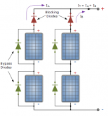
In my experience panels have bypass diodes, not backfeed diodes. My experience isn't that comprehensive but I do have a few different brands / design panels here and none of them had backfeed prevention. In fact one of my test Trina panels, with bypass diodes in the shell on the back, developed a fault during testing and sunk quite a bit of current from the other panels in the array.
 
In my experience panels have bypass diodes, not backfeed diodes. My experience isn't that comprehensive but I do have a few different brands / design panels here and none of them had backfeed prevention. In fact one of my test Trina panels, with bypass diodes in the shell on the back, developed a fault during testing and sunk quite a bit of current from the other panels in the array.
Really... hmmm that's one I haven't seen before. We always recommend fusing panels individually if more than two are connected because we've found the current from 2 can burn out the backfeed diode of a third... but I haven't seen any that don't at least have one. Then again, I've only worked with 8 or so brands myself, and all higher-end(ish), so maybe cutting that out is a common cost-cutting practice?
 
There won't be any current flowing back into the panel if there is a backfeed diode so the diode won't burn out because well, there's no current flowing. This assumes of course that the voltage rating is not exceeded causing the diode to fail but any diode in a panel should be rated to well well beyond any voltage that will be present forward or reverse as lots of panels are spec'd to 1kV and even low end ones to 600V. That tells me that what ever the diode in the panels you have tested is doing, it's not preventing backfeed.

I agree with the fusing too. Backfeed diodes are only a nicety. Diodes have a habit of going short when they do fail, so fuses are the safety device when all else fails.
 
Hmmm to be clear, I'm speaking of what would technically be called a "blocking" diode (my mistake in calling it a "backfeed" diode), which would only generally be rated to 2-3x the VOC rating of the panel and generally 1.4-2x the Isc rating... thus the current of two or more panels under potential STC conditions could short it, and thus why we recommend fusing individually when more than two are connected. This is definitely a separate component than the bypass diode, though they'll obviously both be in the same little enclosure.
...or no? I can't tell if we're talking about the same thing or not :unsure:
 
Gentlemen,
I'm watching your discussion with interest. Thanks for your contributions.
 
Hmmm to be clear, I'm speaking of what would technically be called a "blocking" diode (my mistake in calling it a "backfeed" diode), which would only generally be rated to 2-3x the VOC rating of the panel and generally 1.4-2x the Isc rating... thus the current of two or more panels under potential STC conditions could short it, and thus why we recommend fusing individually when more than two are connected. This is definitely a separate component than the bypass diode, though they'll obviously both be in the same little enclosure.
...or no? I can't tell if we're talking about the same thing or not :unsure:

Blocking, anti-backfeed, same thing, different words. Their function is to prevent current flowing back into the panel (and by panel that means going the wrong way through the leads, making its way across the panel proper in what ever fashion through the cells or through diodes)

The diodes in the box on the back of the panel are to permit current to flow, in the forward direction*, past either the entire panel or part of the panel primarily to reduce the effect of shading, ie they are bypass diodes. There may be 1, 2, 3, or more bypass diodes in the box depending on the arrangement of the cells.

Personally I've not come across a panel with a blocking/anti-backfeed diode in that box, not in my own collection of panels, nor other people's. I haven't seen any panels with tech specs that say they have that arrangement either. That's not to say they aren't out there, my experiences only cover maybe 10 different models of panels, but the fact that pretty much every country and state's regulations require there be at least a fuse in line with strings / panels when there are more than 3 in parallel says that the regulators believe panels without blocking / antibackfeed diodes in them is the norm. It's why you say it too. If there is a blocking/anti-backfeed diode in the panel reverse current just won't flow, assuming of course the diode is intact.

The voltage specs of a blocking/antibackfeed diodes in the box on the panel, or add on, are unlikely to be exceeded as the diode will likely only see the voltage difference across one panel at the worst. If we have 3 panels in a string and one goes to 0 volts, but not open/shorted (highly unlikely but just for the argument) and the other two remain fully functional only that 3 -2 volts will be seen,the diode will not fail as it can handle the full forward voltage/current by definition and has reverse ratings that should handle the application too, ie don't use a '5 amp' diode with a string that can produce 15 amps. These diodes are usually rated at 1kV because that's the typical max series voltage the panels are rated to. Yes there are lower spec'd panels but if you have to produce a diode for 1kV there's no point it also making an assembly for 600V. The price difference is small.

Static is usually what takes out diodes associated with panels.

1573698040290.png

*let's not cloud this with electron flow theory
 
@gnubie hmmmm this is very interesting... and makes sense. I'm going to have to go back to the sensei who taught me about these things and get some clarification, because it definitely contradicts some things that I thought he told me... or, failing that, I'm going to open up a few of the panels we work with and see if what I think is in there is, in fact, actually in there. I know that the Energig SunWare and SpectraLite panels have blocking diodes built-in, but now I'm super curious about our SunPower, Sterling, Victron, and etc panels that we regularly deal with.

I do stand by at least a portion of my original statement, which is that you don't need an isolator between charge sources at the battery because if nothing else the controller does have a blocking diode to prevent current flowing from batt to PV... but even that's only based on the known behavior of Victron, Outback, and MidNite Solar controllers... other controllers may not be so equipped. I've never worried about it much because my impression was -until now- that every panel had backfeed prevention built in already.
 
I posed that question to Renogy a short while ago. They said their panels have always had blocking diodes but not bypass diodes. I just bought two Sunpower 327w panels and now I’m wondering if they also have blocking diodes. I read a while ago some companies are clipping the diodes Inside the box to increase flow.
humm.
 
@gnubie hmmmm this is very interesting...

Indeed. The CC will prevent current from the battery making it's way back into the panels. Diodes there only apply from when people used to hook panels directly to batteries (shudder). Even linear controllers didn't have that issue. If you do find your panels have a blocking diode in them please post the make / model and, if possible, photos of the arrangement of the diodes in the box. I'm really interested to see what actually does have blocking diodes out there.

Thought I'd kick the pictures off, here's a photo of the connection box from the back of a junker panel that has been damaged in transit. It does still work but the glass is shattered so it's not mounted on anything. This one has no blocking diode, only bypass diodes.
 

Attachments

  • box.png
    box.png
    476.7 KB · Views: 12
Last edited:
Not an expert, but Gnubie just posted what it took me 14 years to learn.

Go with redundant systems when you can, batteries strings in parallel for redundancy,
Panels strings in parallel to batteries for redundancy,
I even have inverters in parallel for redundancy.

When your butt is on the line, 2 is 1... 1 is None.
In a boat, cry now at the cost, or cry later when the marine tow bill comes in...

Not all panels come with blocking/back feed diodes.
Without them your battery will heat the panel at night in some systems or failures.

Along with blocking diodes, he shows what I call 'Bridge' diodes, it's simply a bridge over a defective or shaded panel.
One working, one shaded, you get the full power from one, and what ever the second defective/shaded panel can produce.
Otherwise the shaded/defective panel will drag down production to whatever the shaded/defective panel will produce.
If it quits entirely, you get screwed without the bridge in place to bypass the bad panel.

In my experience,
1. Add 20% to the total output of the panel string and size your wires there. That's a 20% maximum safety margin built into your wiring harness, the harness being the hardest thing to change in most cases.

2. Breaker/fuse as close to the power source as is possible.
The fuse at the battery/battery string in your diagram protects the CHARGED wire to the controllers,
Then a battery combiner switch is protected from a shorted battery cable.
A shorter battery cable can very quickly overload battery cables/combiner switch contacts...

The fuse should ALWAYS protect the wiring harness from a 'Supply'/Source of current.
The smaller charge controller wires should have a breaker close to the power supply, like you show, but I would put the smaller breakers closer to the charge controller if that's convienent...

I, personally, would buy a water tight box and put panel disconnects/breakers closer to the panels BEFORE their production hilts the wiring harness.
While it's probably going to take some abuse not being in the main cabin, it's better than to have the wiring in the walls get smoked before a breaker gets tripped...
Closer to the panels it also works for your panel disconnect should they need service.
 
lol.... ok guys, you've skewered me!! For the record, I was a sailor for a long time, but never did any extended sailing. Having multiple panels for the reasons you've stated make perfect sense, I just never thought along those lines, which is why I asked!!! I've been edumucated.

And while the general consensus is to put the switch/breaker by the panels, I'd still put them near the SCC, just for sake of convenience. I get why near the panels is a good thing, but the thought of a switch/breaker outside in the elements doesn't agree with me. I mean, seriously, how many of us have actually seen the wires between the panel and the SCC smoke?
 
If the wires are sized correctly nothing the panels can do will cause them to smoke. There won't be a current path back from the battery to do that either unless the CC catches on fire first.
 
If the wires are sized correctly nothing the panels can do will cause them to smoke. There won't be a current path back from the battery to do that either unless the CC catches on fire first.

I mean, seriously, how many of us have actually seen the wires between the panel and the SCC smoke?

Ever seen what a lightening strike in a marina will do to wiring harnesses?
Sail boats all have those lightening rods sticking up...

A former basket ball pro (Larry Bird) lived in the area and his giant houseboat got an indirect strike,
We had to cut the lines so it didn't pull the dock down with it as it burned...
One thing about sinking, it puts the fire out.
 
Ever seen what a lightening strike in a marina will do to wiring harnesses?
Sail boats all have those lightening rods sticking up...
Not disputing that, lightning can be nasty. But, what does that have to do with placement of a switch and panel wiring under normal conditions? A Lightning strike superceeds all and there isn't much you're going to do about it.
 
I've seen quite heavy coax exploded by lightning, leaving debris all over the walls, ceiling and floor of a concrete equipment room. Several meters of aluminium pipe from the antenna was never seen again.
 
Back
Top