diy solar

diy solar

Seplos CAN BUS RS485 48v 200A 8S-16S BMS

Well I’ve changed the wiring around, tried it on the 485 too and nothing works. Useless piece of chinese rubbish!! May as well leave it on lead acid as it functions fairly well on that.
Thanks for trying.
 
Last edited:
Mine started communicating with the inverter on the first try. CAN communication to an SMA Sunny Boy. The Seplos folks have numbered the RJ45 pins in reverse order in the manual. This does not impact the RJ485 as the pinout are symmetrical.

And for CAN communication you need 3 wires - CAN L, CAN H, and ground. From what I've read it goes the same for RJ485.

It is a long thread (and I'm not going through it) but did you:
1) Set the correct CAN protocol in the Battery Monitor software?
2) Wire the cable correctly? If you know your inverter pinout (I found it out on the previous page) and provide a picture of the cable that you use (with visible cables from the bottom side of the connector) I can verify it is correctly wired.
 
I’ll try and get some pics of the wiring tomorrow ( had a gut full of it today ).
The protocol has no setting for LuxPower or Pylontech in my software. It’s been mentioned previously that it defaults to Pylontech but I have no idea on this. The LuxPower pin out drawing shows no ground.
 
I did a bit more searching on this. Common ground is not required but is recommended. You may end up with a damaged inverter or BMS without it. It depends on how the hardware implementation and if it is galvanically isolated. I'll have to check the spare BMS I have to see if it is galvanically isolated, but from what I've found while I was looking at the PCB it doesn't look to be.

Ignoring that fact - CAN uses the two wires for differential signals. If CAN_H to CAN_L voltage difference is above a certain threshold voltage it is 1, if it is below another threshold voltage - it is 0. So in theory it can work without ground.

The same goes for the RS485. It uses the differential voltage between A and B to determine if it is 1 or 0, but in another manner - it is either A > B or B > A. The voltage difference again needs to be above a certain threshold.


Looking at the "Luxpower Compatible Battery List" - the first entry is "Pylon". I suppose this is the Pylontech protocol. And it states CAN support only, not RS485 for it.

Your wiring when looking on the bottom side of the RJ45 connector at the cable should be as follows:
LuxPower: NC - NC - CAN_L - CAN_H - NC - NC - NC - GND
Seplos: NC - NC - GND - CAN_H - CAN_L - GND - NC - NC

3 wires:
1) LuxPower 3 to Seplos 5
2) LuxPower 4 to Seplos 4
3) LuxPower 8 to Seplos 3 or 6 (one of them is sufficient)

And once you power up your inverter you need to go through the LCD to set up the battery type as Pylontech.
 
Last edited:
I’ll try and get some pics of the wiring tomorrow ( had a gut full of it today ).
The protocol has no setting for LuxPower or Pylontech in my software. It’s been mentioned previously that it defaults to Pylontech but I have no idea on this. The LuxPower pin out drawing shows no ground.
Steve,
Don't forget you need to log in to the BMS software to select the protocol.
Then you can set it at the top RHS of the screen.
 
Mariner62, if you mean the admin/admin login, I’ve already tried that and neither Pylontech or LuxPower are on the drop down.
 
Brum
I’m gonna start from scratch with a new, tested lead but your wiring explanation is what I have already tried. Picked up one of those reusable rj plugs so should be a lot easier.
 
If your wiring is correct then the only missing part is the software settings. Both the BMS and the inverter should be configured to the Pylontech protocol. I don't recall how mine Seplos was looking, but I just choose the SMA entry in the list and it worked as a charm.

Looking at google videos once you click the "CAN" dropdown there should be "Pylon" as the first option, Growatt as the second option, and the list goes by. If you don't see "Pylon" on the top of the list take a screenshot (or picture with the phone) so we can see what options you have there.
 
Righty. Finally got comms. Turned out my first new lead was faulty ( no continuity on the blue wire ) so that’ll teach me to check my leads even if they’re new. Think everything is running ok now and guessing the software is defaulted to Pylontech as it’s not in the drop down
What can I actually do with this Seplos software or is it more a monitoring/ fault finding thing?
 

Attachments

  • 5C2470BB-955A-4A2E-9BD9-E2689BF7D194.jpeg
    5C2470BB-955A-4A2E-9BD9-E2689BF7D194.jpeg
    221.6 KB · Views: 23
  • image.jpg
    image.jpg
    119.5 KB · Views: 23
Hi all. Can anyone recommend the best settings for 280ah, 200A BMS. My cells stop discharging at 24% at the moment. I'm getting the Monomer Low Pressure Alarm. Any ideas?
 
Righty. Finally got comms. Turned out my first new lead was faulty ( no continuity on the blue wire ) so that’ll teach me to check my leads even if they’re new. Think everything is running ok now and guessing the software is defaulted to Pylontech as it’s not in the drop down
What can I actually do with this Seplos software or is it more a monitoring/ fault finding thing?

Soz for this double post, not sure how to delete it.
 
Hi all. Can anyone recommend the best settings for 280ah, 200A BMS. My cells stop discharging at 24% at the moment. I'm getting the Monomer Low Pressure Alarm. Any ideas?

What are the lowest cell voltages at that point? Did you do the top balance of the cells?

The "Monomer Low Pressure" alarm likely means that there are cells below 3V (likely close to 2.5V). The cause for this is either a lack of top balance or your weakest cell is 24% short of the 280Ah capacity. But 24% lower than the 280Ah capacity is ~210Ah. Where did you get that cells from? Did you test the capacity for some of them?
Thanks for answering. Yes I top balanced. I didn't check the capacity, but the supplier was reputable and I've had cells which have been tested at 100% capacity from the same seller.

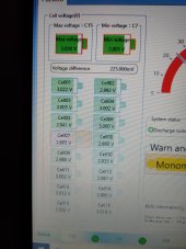
Lowest cell is 2.8V which is what's confusing me. Voltage difference has run quite high though. I'm wondering if a bad cell?!

16747681822281262815131528676348.jpg
 
The highest cell voltage is at 3.03V and the lowest is 2.8V. This does not look like unbalanced cells. And also doesn't look like a major capacity deviation.

Did you charge the battery to the point where the BMS disables the charging to protect the battery from overvoltage? The BMS needs that to calibrate the 100% charge point.
 
It's been running for a few months charging at night up to 100%. That's why I want to check settings to make sure nothing is wrong or incorrect
 
Charging to 100% according to the BMS or charging until the BMS disables the charging? These are not the same if it has never marked the 100% charge point correctly.

My inverter will stop charging when the BMS reports a 100% charge. Even if the cells are at 50% actual charge.

To do the calibration you need a proper charger that does not communicate with the BMS, but terminates charging based on the voltage. Or a power supply capable of delivering 60V.
I'm running a Sofar ME3000SP. I could maybe pull out the comms cable? I don't have a 60V charger
 
If your inverter can work in "open loop" mode you can likely do that. Set proper charging voltage limit. 57.6V should do the job. Monitor the moment when the cells start going over 3.4V to confirm your pack is in good balance. If it is - all cells will quickly go to 3.5V and the to 3.6V. And somewhere at that point, the BMS will disable the charging and set the SOC to 100%.
 
If your inverter can work in "open loop" mode you can likely do that. Set proper charging voltage limit. 57.6V should do the job. Monitor the moment when the cells start going over 3.4V to confirm your pack is in good balance. If it is - all cells will quickly go to 3.5V and the to 3.6V. And somewhere at that point, the BMS will disable the charging and set the SOC to 100%.
I'll have to investigate. I'm not sure what would happen if I pulled the Comms cable. I'll try to charge tomorrow without it and see what happens!
 
Back
Top