diy solar

diy solar

Some Modeling to go with Will's current sharing videos.

FilterGuy

Solar Engineering Consultant - EG4 and Consumers
Joined
Nov 26, 2019
Messages
7,939
Location
Los Gatos CA
Warning: I go full propeller head on this post!!! ?

@Will Prowse just released a couple of videos about hooking parallel batteries together. One commenter claimed 4 batteries in parallel but hooked up 'Diaganaly' would stay balanced. 2 batteries in parallel with diagonal connections is balanced any more in parallel will be out of balance.

I decided to nerd out and try to model the diagonal battery hook-up. (I tried this once before but got wrapped around the axil... I tried a different approach this time and it worked out)

For simplicity, I only modeled 2 in parallel with diagonal connections and 3 in parallel with diagonal connections.

2 Batteries:
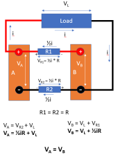
1644391406692.png

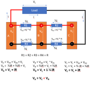
Assume the resistance of the interconnecting cables are all identical and of value R.
Since each battery is only carrying half the current, the cables between the two positive terminals will carry half the total current. Likewise, the current between the two negative terminals will carry 1/2 the current.

To calculate the voltage on battery A, start at the battery A negative terminal and add the voltages as you go around the loop.
Va = The voltage across R2 + Voltage across the load. The voltage across R2 = 1/2 I * R, so the voltage across battery A is VL + 1/2*I*R

Now calculate the voltage on battery B by starting at the Battery B negative terminal and adding the voltages around the loop..... it comes out to 1/2*i*R + V2
So.... the voltages on the two batteries are the same and therefore the load is the same and they are balanced.

Now let's look at 3 batteries.
1644388948942.png

The big difference here is that the current on each of the interconnects is not the same

The positive linkage between Battery C and Battery B is 1/3 of the total current
The positive linkage between Battery B and Battery A is 2/3 of the total current.
Similarly, the interconnects on the negative are 1/3 and 2/3 of the total.
(This turns out to be a good first approximation. It is good enough to prove the point but not 100% accurate... more on this below)

Now when you go around the loop and calculate the voltages you get this:

Va = Vl + i*R
Vb = Vl + 1 1/3*I*R
Vc = Vl + I*R

As you can see, the voltage on battery B is slightly higher than on batteries A and C. This means it will be contributing less current. This is not a balanced arrangement. As you add more batteries, this pattern continues to get worse. The middle batteries will always be stressed less than the outer batteries.

Notice that since the voltages are not the same across all 3 batteries, the current contribution of B will be less than for A and C. This is why I said the 1/3 - 2/3 current model is only a first approximation. However, after doing a sensitivity analysis on the approximation, I concluded that it does not change the model in any significant way.
 
Last edited:
@FilterGuy Will you please re-run your 3 battery model with some actual values rather than theoretical numbers? I'm having a hard time following all the variables.

Also, based on the model, would increasing the wire size as you increase the current further balance things out, aka, decreasing resistance each time you add an additional battery?
 
Last edited:
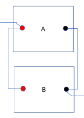
I drew this off the top of my head while I was supposed to be working but here is the way I was taught to connect wet cells back in the day, I carried it forward to SLA and now to the Drop In LFP banks I tinkier with. All wires are equal size & length despite the diagram's shortcomings. The goal being to make the total length of wire for all batteries as equal as possible.

1644421134377.png
 
Yeah after 2 batteries it all starts to wonder around due to the resistance in the cables linking the batteries.
But as Will found out, overall they tend to equalize out over the whole cycle.
Think of it like a circle of kids doing ring a ring a roses !!! Each kids wants to go their own pace (depending how much sugar they had at the party) but ultimatly the ring will go round and round at a balanced pace.
 
Warning: I go full propeller head on this post!!! ?

@Will Prowse just released a couple of videos about hooking parallel batteries together. One commenter claimed 4 batteries in parallel but hooked up 'Diaganaly' would stay balanced. 2 batteries in parallel with diagonal connections is balanced any more in parallel will be out of balance.

I decided to nerd out and try to model the diagonal battery hook-up. (I tried this once before but got wrapped around the axil... I tried a different approach this time and it worked out)

For simplicity, I only modeled 2 in parallel with diagonal connections and 3 in parallel with diagonal connections.

2 Batteries:

View attachment 83062

Assume the resistance of the interconnecting cables are all identical and of value R.
Since each battery is only carrying half the current, the cables between the two positive terminals will carry half the total current. Likewise, the current between the two negative terminals will carry 1/2 the current.

To calculate the voltage on battery A, start at the battery A negative terminal and add the voltages as you go around the loop.
Va = The voltage across R2 + Voltage across the load. The voltage across R2 = 1/2 I * R, so the voltage across battery A is VL + 1/2*I*R

Now calculate the voltage on battery B by starting at the Battery B negative terminal and adding the voltages around the loop..... it comes out to 1/2*i*R + V2
So.... the voltages on the two batteries are the same and therefore the load is the same and they are balanced.

Now let's look at 3 batteries.

View attachment 83061

The big difference here is that the current on each of the interconnects is not the same

The positive linkage between Battery C and Battery B is 1/3 of the total current
The positive linkage between Battery B and Battery A is 2/3 of the total current.
Similarly, the interconnects on the negative are 1/3 and 2/3 of the total.
(This turns out to be a good first approximation. It is good enough to prove the point but not 100% accurate... more on this below)

Now when you go around the loop and calculate the voltages you get this:

Va = Vl + i*R
Vb = Vl + 1 1/3*I*R
Vc = Vl + I*R

As you can see, the voltage on battery B is slightly higher than on batteries A and C. This means it will be contributing less current. This is not a balanced arrangement. As you add more batteries, this pattern continues to get worse. The middle batteries will always be stressed less than the outer batteries.

Notice that since the voltages are not the same across all 3 batteries, the current contribution of B will be less than for A and C. This is why I said the 1/3 - 2/3 current model is only a first approximation. However, after doing a sensitivity analysis on the approximation, I concluded that it does not change the model in any significant way.
Good description, but what Will's video also demonstrated is that when the batteries are of different capacity their internal resistance is different, and this can compound the effects of the different resistance on the interconnects.
 
I'm guessing that a 0.05C charge/discharge power level behaves differently than a constant 0.3C power level. My powerwall is ~ in the 0.05C to 0.1C operating range.

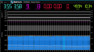
I make this comment this because I have 6 batteries of 48v@260ah in parallel with 4/0 wire and main +/- on apposing diagonal edges of the rectangle. This 6 x parallel battery bank is monitored by Batrium which gives good visibility in to each of the 84 individual packs - and I haven't seen any issues with current flow per pack and I'm into year 3 of daily charge/discharges.
1644423128508.png

If I were to try routing charge/discharge at 0.3C - I think things might not be as smooth. So I wonder if the level of C is a key piece of this discussion - e.g. you can reduce issues by building a larger battery bank?
 
Last edited:
I'm guessing that a 0.05C charge/discharge power level behaves differently than a constant 0.3C power level. My powerwall is ~ in the 0.05C to 0.1C operating range.

I make this comment this because I have 6 batteries of 48v@260ah in parallel with 4/0 wire and main +/- on apposing diagonal edges of the rectangle. This 6 x parallel battery bank is monitored by Batrium which gives good visibility in to each of the 84 individual packs - and I haven't seen any issues with current flow per pack and I'm into year 3 of daily charge/discharges.
View attachment 83096

If I were to try routing charge/discharge at 0.3C - I think things might not be as smooth. So I wonder if the level of C is a key piece of this discussion - e.g. you can reduce issues by building a larger battery bank?
You just redefined a low C rate for me. I was thinking 0.1 to 0.3 was a low C rate with a high C rate not beginning until closer to 1 C. Perhaps my understanding is off, is there a standard understanding of Low Med High in this context that I've missed?
 
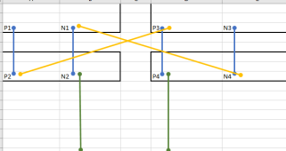
I drew this off the top of my head while I was supposed to be working but here is the way I was taught to connect wet cells back in the day, I carried it forward to SLA and now to the Drop In LFP banks I tinkier with. All wires are equal size & length despite the diagram's shortcomings. The goal being to make the total length of wire for all batteries as equal as possible.

View attachment 83091
Hmmm. I redrew that to try to understand it.
1644425303402.pngI don't think that would be balanced.

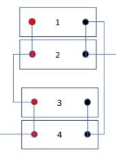
At first, I thought you were drawing what victron calls 'halfway'
1644425519580.png
Halfway works well because it builds block of two.

If you look at the drawing of halfway, you can see that 1 & 2 are wired as diagonal... so they stay balanced in relation to each other.
3 & 4 are also a balanced pair.

Lets think of each set those two pairs as a internally balanced 'mega batteries' A&B

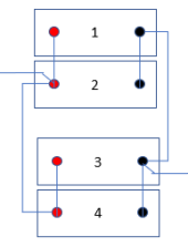
1644426054392.png
Notice that Mega A & B are wired diagonal as well. Consequently, the overall arrangement is balanced. This is a neat trick but only works for certain battery counts in powers of two. (4, 8, 16, 32, etc)
 
Hmmm. I redrew that to try to understand it.
View attachment 83099I don't think that would be balanced.

At first, I thought you were drawing what victron calls 'halfway'
View attachment 83100
Halfway works well because it builds block of two.

If you look at the drawing of halfway, you can see that 1 & 2 are wired as diagonal... so they stay balanced in relation to each other.
3 & 4 are also a balanced pair.

Lets think of each set those two pairs as a internally balanced 'mega batteries' A&B

View attachment 83101
Notice that Mega A & B are wired diagonal as well. Consequently, the overall arrangement is balanced. This is a neat trick but only works for certain battery counts in powers of two. (4, 8, 16, 32, etc)
That is what I meant to draw, my bad for trying to do it quick at the desk. I put the load leads in the wrong place they should be P2 and N4. So long as the cables are the same it makes no difference if the interconnects are 1 - 3 and 2 - 4 or 1 -4 and 2 -3.
To my knowledge there is no way to do "odd" number sets without a bus bar or some common terminator
 
Last edited:
But as Will found out, overall they tend to equalize out over the whole cycle.
I am not sure exactly which part of the video you are referring to. He did talk about the fact that if you fully recharge each day they will all eventually get back to full charge. That is true, but that does not change the fact that some discharged more than others.

The other thing he observed is that the current differential between the batteries went down as that batteries entered the flat part of the charge curve. That was interesting but observe two things: 1) There was still a differential and 2) Initially there was a large differential. Consequently, some batteries are getting used more than others... What I can't say definitively is how bad the effect is on them. As will points out, with solar calendar aging may be the larger reason for batteries to go out.
 
You just redefined a low C rate for me. I was thinking 0.1 to 0.3 was a low C rate with a high C rate not beginning until closer to 1 C. Perhaps my understanding is off, is there a standard understanding of Low Med High in this context that I've missed?
I don't know of common definitions. My point is I suspect the operational C rate of a battery bank makes a big difference in this discussion.

In my case, I don't see any issues with my battery bank - and I'm suggesting that it might be because of the 'low' C rate. But maybe it's a happy accident.

So I'm wondering if more knowledgeable folks would agree that the higher the C, the more pronounced the affects - and are there actual numbers to characterize this?
 
I'm guessing that a 0.05C charge/discharge power level behaves differently than a constant 0.3C power level.
Yes.... and no. If you look at the model, the battery voltage looks something like this:

Va = Vl + i*R
Vb = Vl + 1 1/3*I*R
Vc = Vl + I*R

Notice that the V-load is the same for all 3 and the factor that changes is some product of current and cable resistance.
If the current is very low, the voltage difference is very low so the imbalance is very low.
So, the behavior is the same for low currents, but the effect is very low.

So I'm wondering if more knowledgeable folks would agree that the higher the C, the more pronounced the affects
Correct.

and are there actual numbers to characterize this?
Will's video had some numbers.

I looked up 2 AWG copper and it is .1563 Ohms per 1000 ft or .0001563 ohms per foot.
Let's assume the interconnects are one foot long so the interconnects are .0001563 ohms. However, we have the crimps and terminal connections to worry about so let's double it: .0003126 ohms.

Let's assume we are driving 100 A. In the model, the *difference* in voltage is 1/3IR so that is 1/3 * 100 * .0001563 = .01042 Volts.
That seems low but 1) I had to make a LOT of assumptions to get the number. It could be off by several multiples. (I suspect the resistance on the battery posts is a lot higher than I allotted for) 2) the number is starting to get in the ballpark of making a difference
 
Also, based on the model, would increasing the wire size as you increase the current further balance things out, aka, decreasing resistance each time you add an additional battery?
Yes, the voltage difference in the model is some factor of current and resistance. If the resistance goes to a theoretical zero, the effect would go to zero no mater what the current is. Conversely, as the current approaches zero the effect approaches zero no matter what the resistance is.

In the video @Will Prowse said something to the effect of "I like to use wire twice the size of what is needed". By doing this, he significantly reduces the resistance and that reduces any effect of an imbalanced arrangement.
 
I looked up 2 AWG copper and it is .1563 Ohms per 1000 ft or .0001563 ohms per foot.
Let's assume the interconnects are one foot long so the interconnects are .0001563 ohms. However, we have the crimps and terminal connections to worry about so let's double it: .0003126 ohms.

Let's assume we are driving 100 A. In the model, the *difference* in voltage is 1/3IR so that is 1/3 * 100 * .0001563 = .01042 Volts.
That seems low but 1) I had to make a LOT of assumptions to get the number. It could be off by several multiples. (I suspect the resistance on the battery posts is a lot higher than I allotted for) 2) the number is starting to get in the ballpark of making a difference
I've used the same NEC wire resistance tables. However I will give you an example that I still can't quite explain.

I had about 8 ft of 2 AWG wire (round trip) between a Victron Multiplus and a 4S2P battery bank, charging at about 70A. All connections were with well crimped copper lugs tightened down to all terminals. The charge profile seemed to not be working as expected. I then checked the voltages at the multiplus and at the battery bank. The difference was over 0.3V. That was enough to cause the Multiplus to eventually drop out of absorption and into float before the battery had even reached the full charge voltage.

I checked everything multiple times. Didn't make sense. For that big of a drop at 70A should have required almost over 30 ft of wire.
 
I am not sure exactly which part of the video you are referring to. He did talk about the fact that if you fully recharge each day they will all eventually get back to full charge. That is true, but that does not change the fact that some discharged more than others.

The other thing he observed is that the current differential between the batteries went down as that batteries entered the flat part of the charge curve. That was interesting but observe two things: 1) There was still a differential and 2) Initially there was a large differential. Consequently, some batteries are getting used more than others... What I can't say definitively is how bad the effect is on them. As will points out, with solar calendar aging may be the larger reason for batteries to go out.
I defiantly formed the opinion from the video that the batteries eventually fully charge and discharge. Some work harder at the start but they all catch up.
Again think about the ring of kids. The big sugared up kid pushes the ring to start and soon all the little lids catch up.
Or think about multiple LA batteries in a pack, we know 1 weak one will hurt the output of the whole pack, but the pack does not stop dead, the others limp it along.
 
I've used the same NEC wire resistance tables. However I will give you an example that I still can't quite explain.

I had about 8 ft of 2 AWG wire (round trip) between a Victron Multiplus and a 4S2P battery bank, charging at about 70A. All connections were with well crimped copper lugs tightened down to all terminals. The charge profile seemed to not be working as expected. I then checked the voltages at the multiplus and at the battery bank. The difference was over 0.3V. That was enough to cause the Multiplus to eventually drop out of absorption and into float before the battery had even reached the full charge voltage.

I checked everything multiple times. Didn't make sense. For that big of a drop at 70A should have required almost over 30 ft of wire.
yup.... Like I said, I suspect my estimate for the resistance of the crimps and connections is probably way too low.

In your case .3V @ 70A means the resistance is .0043 ohms That is over an order of magnitude greater than in my estimate.
 
I looked up 2 AWG copper and it is .1563 Ohms per 1000 ft or .0001563 ohms per foot.
Let's assume the interconnects are one foot long so the interconnects are .0001563 ohms. However, we have the crimps and terminal connections to worry about so let's double it: .0003126 ohms.

Let's assume we are driving 100 A. In the model, the *difference* in voltage is 1/3IR so that is 1/3 * 100 * .0001563 = .01042 Volts.
That seems low but 1) I had to make a LOT of assumptions to get the number. It could be off by several multiples. (I suspect the resistance on the battery posts is a lot higher than I allotted for) 2) the number is starting to get in the ballpark of making a difference
The resistance of the copper is almost nothing in this problem, it is all down to the connections. I bet a thermal camera on Wills warm cables would have shown they were hotter at the ends.
Of all the burned up wiring I have seen in industrial machines over the years, it is ALWAYS the connecting ends that have burned, not the middle of the cable.
 
Yes, the voltage difference in the model is some factor of current and resistance. If the resistance goes to a theoretical zero, the effect would go to zero no mater what the current is. Conversely, as the current approaches zero the effect approaches zero no matter what the resistance is.

In the video @Will Prowse said something to the effect of "I like to use wire twice the size of what is needed". By doing this, he significantly reduces the resistance and that reduces any effect of an imbalanced arrangement.
Some server rack batteries come with 6 gauge wire. These conductors are meant to connect a server rack pack with a bus bar.

I used 2 gauge copper in my video. This is the largest conductor I could safely attach to the terminals.

Imagine if someone used 6 gauge copper conductors (that come with some of the batteries) to put multiple packs in parallel! Yikes!
 
The resistance of the copper is almost nothing in this problem, it is all down to the connections. I bet a thermal camera on Wills warm cables would have shown they were hotter at the ends.
Of all the burned up wiring I have seen in industrial machines over the years, it is ALWAYS the connecting ends that have burned, not the middle of the cable.
The cable itself was actually very hot. You are correct, typically its the connection. Very common issue.

My lugs were nearly the same temperature as the conductor, from what I could feel.

But whether it was the connection or the conductor, the cables were well made and over sized, and there were still current sharing issues. I do not know how to calculate the interconnection losses between the lugs, but this is a factor as well. I would assume that with the crimper I used, the terminations were gas tight cold welds. But again, more factors going against you.

This is why bus bar w/ equal length conductors connecting the server racks is the best method.

I have used the diagonal configuration for ages in past packs, and I always had these issues.
 
This is why bus bar w/ equal length conductors connecting the server racks is the best method.

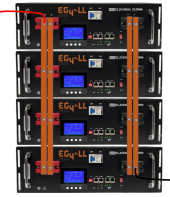
Here is an idea that might be even better:

1644438116880.png

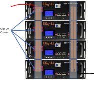
I am not sure how wide the connectors on the EG4 battery is, but you might have to go extra thick on the busbar to get enough copper. (The busbars need to be big enough that there is little resistance and therefore minimizes the potential problem. Otherwise it is just exchanging the problem with wires for the same problem with Busbars.

Note: You would want some kind of cover or heatshrink over all that bare copper.

The downside of this idea is that you have to remove all the busbars if you need to swap out one of the batteries.

Unfortunately, most of the other server rack batteries put the breakers or screen or com-ports in the way. Even the LiFePower4 has stuff in the way.

@Will Prowse: If you have any contacts at the various companies, you might want to pass this idea on to them so they build the batteries to accommodate the idea. They could even sell Pre-made busbars and some kind of clip-on covers for the busbars

1644438889872.png
 
Back
Top