diy solar

diy solar

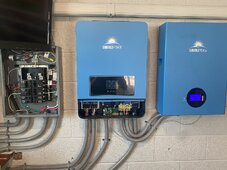
SUNGOLD 10KW 48V SPLIT PHASE SOLAR INVERTER WONT START UP RED LIGHT ON BOARD

Sungold upheld their warranty and I’ve installed my replacement they sent. Everything here working as it should be. Given I make it awhile I am happy with Sungolds ability to maintain communication with me and to send me a replacement system. Still a great value given I last awhile. If I can maintain no major problems I plan on purchasing additional SG gear

F00EB142-0328-4B8C-885A-4A89519B50E4.jpeg73473BF9-44D6-494E-AC77-BDC220A3AEFE.jpeg56576354-2DCD-4856-A506-5AC202D7B7F4.jpeg
 
Sungold upheld their warranty and I’ve installed my replacement they sent. Everything here working as it should be. Given I make it awhile I am happy with Sungolds ability to maintain communication with me and to send me a replacement system. Still a great value given I last awhile. If I can maintain no major problems I plan on purchasing additional SG gear

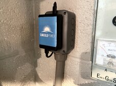
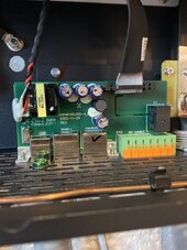
View attachment 184585View attachment 184586View attachment 184588
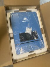
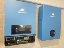
Looks like the colors match better?
Notice any other difference in the display outside of shape?
 
Looks like the colors match better?
Notice any other difference in the display outside of shape?
This unit is what I expected the original to be and wasn’t. This unit was sealed in its plastic with a silica pack which my old unit didn’t. I see no cosmetic issues, dust, finger prints etc, and this unit had a plastic film over display, original did not. I have a better feeling about this system

Yes color more accurate
Yeah, I was gonna say, "Nice Silica Stephanie!"
 
Is it up and running?

WooHoo!!! Glad they came through even if it did take the Iron Fist of Visa to make it happen!
 
Yep...workin' fine here.

I don't know that it's even related but I got a #12 Communication error yesterday (2nd time in two months) and had to completely restart (i.e. ac off, solar unplugged/off, batteries off) to clear it but it's working fine and I have no idea if it is even related to the usb port or the RS485 port or something internal... Cindy Lou Who's explanation didn't explain anything more than was already in the manual.

I wouldn't run without it...would feel like being blind...
Based on what that SG “engineer” Cindy CC into our emails awhile back, they appear worrisome over the onboard serial inverters in SRNE ASFs, very similar to what Duane at SA said awhile back:

It looks like you have a QinHeng Electronics CH34 serial converter. This converter has been shown to be quite problematic at times, while it can sometimes work it tends to give errors over time. Those chips tend to give system-level messages in the Kernel Logs (Configuration Tab > Scroll down to USB Devices > Click "view detail"). There are three possible factors that may be affecting it:
1) USB chip: we suggest FTDI instead whenever possible. If this is a direct USB cable to inverter, then it's not changeable and we would advise looking into alternative connection methods.
2) The USB power supply bus is malfunctioning due to too much load or voltage spikes from the device. It is recommended to try one cable at a time or test using a USB extender that has its own independent power supply.
3) Lastly, you can try placing ferrite rings around the USB cable to prevent interference.

I am going to run a month then fire up SA. I wish I could get on that comm board via serial and do my conversions on a trusted external device. I am going to try and take my own advice… and the same advice @Crowz gave me the night he called me… if it’s working… step away and let it run!

image.jpg
 
I'm not gonna worry too much about it unless it becomes a frequent thing...then...
Yeap small price to pay for the data you’re able to gather.. have you done much on your install? I haven’t seen many pictures recently, are you still ground mount outside?
 
Yep. Added the Battery Breaker/disconnect.... moved the three panels around a bit to make space for the two more arriving next week. Still unsure about placement... I think they are pretty 'optimal' where they are and may do a more permanent setup with come concreted in posts and wooden supports. Probably not to spring at least though.

Just got my November Xcel Bill and the electric portion was about 50% less than last year with about the same weather conditions/temps/etc.
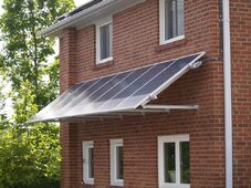
I know it’s not a great idea but I’ve got a southern wall that gets a lot of sun. I’m theorizing tossing up something like this… haven’t decided
46E0616F-D6F3-46E9-B072-F46B3DB9CC01.jpeg
I’m still hesitant to go to the roof
 
Don't want to lead you the wrong way, but I think there are many people using SA with this inverter and it's different models. I'm using an older Raspberry Pi not the 'official one' you have but ...

I think the issue you had was just because that was a bad/reconditioned inverter....
 
EG4 LifePower4 batteries actually have two RS485 (modbus) serial busses (as well as a CAN bus).
Pins 1 and 2 (orange/white and orange, normal ethernet) form one bus.
Pins 7 & 8 (brown/white and brown, normal ethernet) form the second bus.

If using the EG4 Communications hub:
The hub polls the batteries on pins 7 and 8. Any other communications on these pins such as to SA will generally fail due to traffic congestion on the bus. SA will work fine if you use pins 1 and 2.

If using one EG4 Battery set to Address 0 (all dip switches down):
This places the BMS in host (or master) mode. The BMS polls the other batteries on pins 7 and 8. Any other communications on these pins such as to SA or the inverter will generally fail due to traffic congestion on the bus. SA and/or the inverter will work fine if you use pins 1 and 2. The inverter must support the EG4 BMS (Narada) communications protocol. SA does support this protocol, SunGoldPower does not.

The SGP 10K Inverter BMS RJ45 connector uses pins 7 & 8.
The SGP 10kw Inverter Wifi RJ45 connector uses pins 7 & 8. Pins 1 & 2 are 5vdc power for the Wifi dongle. SA can read the inverter status from this RJ45 jack. It is what I use as the USB to RS485 converter provides some isolation.

I have six batteries in a rack. Battery addresses are 1 thru 6.

I am using an EG4 communications hub between the battery stack and a SunGoldPower 10kw inverter as the inverter does not support the BMS (Narada) communications protocol.communications protocol.
Most inverters want to see 0x46 as the device code in the communication data and EG4 uses 0x4A. There are several other differences in the data as well. The hub solves these issues.

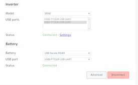
I have the Wifi RJ45 port on the inverter pins 7 and 8 (ensure pins 1 and 2 are cut/not connected as they have 5vdc and ground for the dongle power) into an USB to RS485 converter plugged into one SA usb port.
I have one RJ45 port on the bottom battery in the stack using pins 1 and 2 into an USB to RS485 converter plugged into one SA usb port.

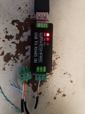
I use two USB to RS485 converters. I have cat5 cables (pre-made commercial) in which I have cut off the RJ45 connector on one end, stripped back the insulation and connected the required two wires (orange/white and orange or brown/white and brown). I use short USB cables from the converters to SA for my use as the SA ports are to close for two converters as I use one USB port for a 10 inch touch screen display.

SA shows all six batteries and also shows all inverter stats including the SOC as reported by the hud to the inverter.
The hub also lets the inverter know what the bulk charge voltage is and this is settable on the hub as "Max Charge Voltage". The "Max Charge Current" can also be set at the hub.

Updated the EG4 LifePower4 battery firmware from 3.10 to 3.32
The baud rate on pins 7 & 8 changed to 19200 while the baud rate on pins 1 & 2 remained at 9600
I updated the EG4 Communications Hub from 1.8 to 1.10. Since the hub talks to the BMS on pins 7 & 8 the baud rate of the hub needs to be updated to 19200 as well. If I update the baud rate on the hub with the 1.8 firmware (I have two hubs) to 19200 it will also communicate with the batteries.

Likewise depending on which two wires you are using the BMS_Test software baud rate also needs to be adjusted accordingly.

This link is to a spreadsheet with the parameter settings for the EG4 Lifepower4 batteries. Addresses 1 thur 5 have firmware 3.32 and Address 6 has firmware 3.10
BMS Version Comparision
 

Attachments

  • SA_Config.png
    SA_Config.png
    30.2 KB · Views: 2
  • USB_RS485.jpg
    USB_RS485.jpg
    105.3 KB · Views: 2
EG4 LifePower4 batteries actually have two RS485 (modbus) serial busses (as well as a CAN bus).
Pins 1 and 2 (orange/white and orange, normal ethernet) form one bus.
Pins 7 & 8 (brown/white and brown, normal ethernet) form the second bus.

If using the EG4 Communications hub:
The hub polls the batteries on pins 7 and 8. Any other communications on these pins such as to SA will generally fail due to traffic congestion on the bus. SA will work fine if you use pins 1 and 2.

If using one EG4 Battery set to Address 0 (all dip switches down):
This places the BMS in host (or master) mode. The BMS polls the other batteries on pins 7 and 8. Any other communications on these pins such as to SA or the inverter will generally fail due to traffic congestion on the bus. SA and/or the inverter will work fine if you use pins 1 and 2. The inverter must support the EG4 BMS (Narada) communications protocol. SA does support this protocol, SunGoldPower does not.

The SGP 10K Inverter BMS RJ45 connector uses pins 7 & 8.
The SGP 10kw Inverter Wifi RJ45 connector uses pins 7 & 8. Pins 1 & 2 are 5vdc power for the Wifi dongle. SA can read the inverter status from this RJ45 jack. It is what I use as the USB to RS485 converter provides some isolation.

I have six batteries in a rack. Battery addresses are 1 thru 6.

I am using an EG4 communications hub between the battery stack and a SunGoldPower 10kw inverter as the inverter does not support the BMS (Narada) communications protocol.communications protocol.
Most inverters want to see 0x46 as the device code in the communication data and EG4 uses 0x4A. There are several other differences in the data as well. The hub solves these issues.

I have the Wifi RJ45 port on the inverter pins 7 and 8 (ensure pins 1 and 2 are cut/not connected as they have 5vdc and ground for the dongle power) into an USB to RS485 converter plugged into one SA usb port.
I have one RJ45 port on the bottom battery in the stack using pins 1 and 2 into an USB to RS485 converter plugged into one SA usb port.

I use two USB to RS485 converters. I have cat5 cables (pre-made commercial) in which I have cut off the RJ45 connector on one end, stripped back the insulation and connected the required two wires (orange/white and orange or brown/white and brown). I use short USB cables from the converters to SA for my use as the SA ports are to close for two converters as I use one USB port for a 10 inch touch screen display.

SA shows all six batteries and also shows all inverter stats including the SOC as reported by the hud to the inverter.
The hub also lets the inverter know what the bulk charge voltage is and this is settable on the hub as "Max Charge Voltage". The "Max Charge Current" can also be set at the hub.

Updated the EG4 LifePower4 battery firmware from 3.10 to 3.32
The baud rate on pins 7 & 8 changed to 19200 while the baud rate on pins 1 & 2 remained at 9600
I updated the EG4 Communications Hub from 1.8 to 1.10. Since the hub talks to the BMS on pins 7 & 8 the baud rate of the hub needs to be updated to 19200 as well. If I update the baud rate on the hub with the 1.8 firmware (I have two hubs) to 19200 it will also communicate with the batteries.

Likewise depending on which two wires you are using the BMS_Test software baud rate also needs to be adjusted accordingly.

This link is to a spreadsheet with the parameter settings for the EG4 Lifepower4 batteries. Addresses 1 thur 5 have firmware 3.32 and Address 6 has firmware 3.10
BMS Version Comparision
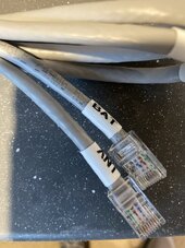
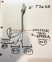
Nice that’s a smart work around with the hub. I modded my cable like this based on a mixture of what support told me and what several users on here said to do. This is my connections between SG ASF 10k inverter to SG L16 Powerwall,

I severed blues and oranges

2AFBBE1A-C630-4F57-8EB3-E039629887A7.jpeg
 
Back
Top