diy solar

diy solar

Use Main Panel as Critical Loads Panel?

This is why I concluded that if you want to save money with an autotransformer, and you can do it safely, you are best served by using your superior brain and energy to make more money and buy a system that doesn’t need one.
I applaud your pragmatism!
I’m only doing this for a hobby, and I assure you I’m not saving any money on it.

Keeping things simple is a much more sane approach in the long run.
 
I applaud your pragmatism!
I’m only doing this for a hobby, and I assure you I’m not saving any money on it.

Keeping things simple is a much more sane approach in the long run.
Well if I use an AT I’m doing it for self education and to flex on people, not to save money.

I have yet to have the bravery to do solar stuff that doesn’t at least break even. I’m willing to bend the rules and ignore time value of money.

Pragmatically I also don’t like systems that assume I’m around (alive, healthy, and of sound mind) to keep operating. I don’t want my system to melt down at the same time I have other important shit to do in life. (much more likely than if I get hit by a bus, but that can happen too).
 
Right, and since the autotransformer winding is pure inductance, the power factor is 0, and thus the consumed power is 0W! :p

Except in the inverter, which has to run 1/8A through inductor and FETs.

I guess I need a power factor meter to know for sure, don’t know the winding resistance.

Or a scope.
Or clamp ammeter on battery, compare with/without autotransformer connected.
Resistance of course could be measured with DC.

I installed critical subpanels with main breakers interlocked with a double pole breaker at the top of the panel.
This was cheaper, easier, and more flexible (at least for me).
This avoids the 120% issue, as the power can only come from one place at the top of the panel by mechanical limitation.

Output of inverter of course goes there.
Backfed input is the one subject to 120% rule.

My main panel definitely has a 120% limitation on the breaker at the end of the panel that provides power to my inverters, but only if I choose to backfeed, which I don’t.

Mine is primarily grid-tie, so I do.

Line-side tap would get around that, but likely has a max current allowed.
The place I'm working on now, I just mounted a 200A main breaker only panel and meter and weatherhead.
With Polaris connectors it will fan out to PV disconnect and breaker panels.

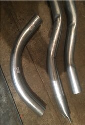
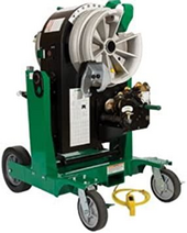
Was going to S-bend my own 2" EMT, but they kinked badly. Turns out that is a common problem, possibly can be dealt with using correct parts on the Greenlee, correctly adjusted, no lubricant. But more likely cheap conduit. People were complaining about that a decade ago. So I punted and ordered a bunch of 45 degree elbows.


This is why I concluded that if you want to save money with an autotransformer, and you can do it safely, you are best served by using your superior brain and energy to make more money and buy a system that doesn’t need one.

I resemble that remark!

?? ⚡⚡ 1703729835660.png

The integrated ATs are fine, somebody at a NRTL checked it so obviously no one is going to die (at a socially unacceptable probability at least).

I'm not going to put full faith in them. Maybe it was done right, but I will withhold judgement until I study it.
 
So, in my procedure I mentioned 2 things. 1) turning off the main breaker (from the utility) and 2) turning off all other breakers in the main panel.

The second step, prevents the inverter from "getting power" from the main panel, where it would essentially just be feeding itself.

The gist of it is, all breakers in the main panel are off, then I turn on the generator breaker, and whichever *individual* loads I want to power up. In my case, my battery bank isn't large enough to feed the whole house for any extended period of time (maybe half a day, max), and my inverter is certainly not large enough to run the whole house (central AC and such) so the critical loads panel has my "must haves", and I have identified what each breaker in my main panel controls. So, if I want to run my oven temporarily, or a washer/dryer, or a pool pump, etc.. I turn on that individual breaker manually. Then when I'm done, I turn it off. I call it my "nice to have" circuits.
@n2aws thanks for the reply. I’ve been struggling on how to get power to my oven in an outage if needed but can’t easily move oven circuit to critical loads panel. You solved my issue. Thank you. Hitting up Lowe’s tomorrow, lol.
 
Is there anything wrong (i.e. against any code) with feeding the output of a grid tie inverter (Growatt MIN144000TL) back to the main service panel through a "generator" circuit breaker and a manual* transfer switch? The circuit breaker would be interlocked with the main breaker of course.
if your local code allows mechanical interlocks on your main breakers for generators, and you wire the generator breaker to an inlet (maybe an L14-30), what you plug in there is your business. I’ve done exactly this with two subpanels with main breaker interlocks (but I did 50A inlets).

The inlet is unpowered when grid is selected, and the grid is disconnected when the generator is selected.
Lots of people have this setup, and it‘s much safer than just backfeeding the grid and killing someone.
And, it‘s the Law.

Since you are fine with manually switching over during a power failure, this should work for you.
You could even make cables to plug into the Growatt or the generator as needed.
Or add boxes and switches, whatever you like better.

*I don't want automatic transfer because some loads would kill the backup battery, but are still needed occasionally. For example the aerobic septic system. If the power goes out I don't want the septic system aerator to be on 24/7. I want to control it manually to conserve battery life.
Makes sense to me.
 
Except in the inverter, which has to run 1/8A through inductor and FETs.
that’s true, hmmm

Or a scope.
Or clamp ammeter on battery, compare with/without autotransformer connected.
Resistance of course could be measured with DC.
i’ll make a better measurement next time it is torn apart (hopefully not soon).
Like the ammeter on battery approach, thanks!

Was going to S-bend my own 2" EMT, but they kinked badly. Turns out that is a common problem, possibly can be dealt with using correct parts on the Greenlee, correctly adjusted, no lubricant. But more likely cheap conduit. People were complaining about that a decade ago. So I punted and ordered a bunch of 45 degree elbows.
I admit to doing 1” EMT stub bends that came out looking ok.
The others were less successful, and I’ve hidden them so no one sees (they are not in use)!

I don‘t do this for a living, but EMT seems awfully crappy compared to Rigid RMC.
So I also punted bought the 45s and 90s and couplers. ?
 
Outside for a different place I was bolting together rigid.
For basement, I figure EMT is good enough, about as thick as the boxes. costs about $40 vs. $100, and If I was able to make one-piece S-bends it would be pretty simple and economical.

My Greenlee worked fine for 2" rigid. you can see how badly it kinked 2" EMT, compare to a purchased elbow. I wanted to make S-bends for about 7" or so jog, conduit from boxes I mounted outside comes through between joists, and I'll be mounting a wiring box under the joints where I can scramble wires from one box to another.
Small stuff I can bend with a hand bender, and from what I read these benders work OK on those.

EMT 2in bends cropped IMG_4439.jpg 1703735432430.png


He did mention using an interlock between the main and the Gen input breaker.
Sorry for the confusion, I wasn't sure how to draw the interlock for the generator/inverter input to the main panel, but I will install one. Also, the AC disconnect is there since I think my POCO will require it.
 
Another way to do this is to use the ATS (which is required, it provides the neutral forming), but have a transfer switch / critical loads panel with per-circuit transferring etc downstream of it to pull in the circuits that you might need. This also deals with the AC disconnect problem because the ATSUS handles this.
Wow, I missed the fact that it needed extra hardware in addition to a battery to support battery backup. Looks like they make two versions, the ATSUS (about $500) and ATS-SYN (about $800). Even with the needed ATS, it still comes out cheaper than any other split phase hybrid I could find that is approved by my POCO.

Now I need to read the rest of the posts here to see what else I missed!
Are you talking about the min 11400 tl xh-us?

It uses a propriety, expensive battery system. The aro battery is about $5500 per 10kwh. And it's limited to about 5kw output. How much battery and backup output do you need?
 
If there are two AC sources tied together (IE with a hybrid inverter) then closer analysis is needed.
Maybe there are things I don't understand in my own sketch:) Anyway, I don't see how I could have two AC sources tied together. First, there is an interlock on the main breaker and also because of the changeover switch, it can only select one input at a time and it breaks before makes since you have to pass through the "off" position.

Haven't finished reading the comments, but I do see that I will need one of those ATS since there is no neutral from the inverter when on backup. I guess they did it that way since there is no internal transformer. Saving $.
 
you are best served by using your superior brain and energy to make more money and buy a system that doesn’t need one.
I clearly failed that test. I based my decision partly on a neighbor who loves his Growatt. However, his setup doesn't have battery backup. The only other inverter I could find that met my criteria was the EG4 18KPV but for 3 times the price. The Growatt is on order but I haven't taken delivery yet, so are there other hybrid split phase options for $2K or less?
 
Maybe there are things I don't understand in my own sketch:) Anyway, I don't see how I could have two AC sources tied together. First, there is an interlock on the main breaker and also because of the changeover switch, it can only select one input at a time and it breaks before makes since you have to pass through the "off" position.
This was in response to the other member's question.
Haven't finished reading the comments, but I do see that I will need one of those ATS since there is no neutral from the inverter when on backup. I guess they did it that way since there is no internal transformer. Saving $.
Internal transformer is one topology, another one is to have two 120V inverters stacked inside. There might be a slightly newer Growatt hybrid that can directly output 120/240. Not sure about ARO compatibility.
 
I clearly failed that test. I based my decision partly on a neighbor who loves his Growatt. However, his setup doesn't have battery backup. The only other inverter I could find that met my criteria was the EG4 18KPV but for 3 times the price. The Growatt is on order but I haven't taken delivery yet, so are there other hybrid split phase options for $2K or less?
This comment was referring to folks that DIY their own AT to get 120/240 from 120V or 230V equipment.

For grid-tie to make your POCO happy, not that many options.

EDIT: My gameplan is to check again in 6-12 months to see what materializes by then. There's no reason something like EG4 6000XP can't be made completely on-grid legal for basically the same price.

For off-grid, SRNE10K and EG4 6000XP are 48V options that are 120/240 around $1500, there are some big threads about it here (more than this Growatt AFAIK). They do not require MID.
 
The gist of it is, all breakers in the main panel are off, then I turn on the generator breaker, and whichever *individual* loads I want to power up. In my case, my battery bank isn't large enough to feed the whole house for any extended period of time (maybe half a day, max), and my inverter is certainly not large enough to run the whole house (central AC and such) so the critical loads panel has my "must haves", and I have identified what each breaker in my main panel controls. So, if I want to run my oven temporarily, or a washer/dryer, or a pool pump, etc.. I turn on that individual breaker manually. Then when I'm done, I turn it off. I call it my "nice to have" circuits.
This is why I don't want an Automatic Transfer Switch.
 
I'm following the HYS-7.6LV-USG1 thread to see how Hoymiles's first hybrid offering will work out, but the only person playing with it so far on this forum is the distributor. It's LV which has a lot better compatibility with misc accessories. To be clear, it's not like I'm eagerly awaiting any specific model, just the general concept that stuff would be cheaper ;-)

Very similar to other inverters around the $1500-2000 price point. Manual isn't as good as it could be.


I don't see any US retail store yet selling either the hybrid or the battery.
 
Are you talking about the min 11400 tl xh-us?
Yes.
It uses a propriety, expensive battery system. The aro battery is about $5500 per 10kwh. And it's limited to about 5kw output. How much battery and backup output do you need?
I had an alternate plan for battery backup because of the high cost of those Growatt batteries. But then my local supplier had 10 kwh LG batteries they were discontinuing and I got it for $2500. They are listed as compatible with Growatt. I would rather have 48V batteries so can roll my own, but Growatt won't work with them. 5kw output is plenty for me for critical loads.

My alternate plan (which I can still use if needed for extended outages) is to tap into the battery of my Tesla model 3. I and others have successfully pulled 1000 watts from it without the car hiccuping. It will supposedly tolerate up to 2500 watts. With a 75kwh battery, that will last a good while.
 
Back
Top