diy solar

diy solar

Victron Multiplus II 5kVA

Captain Kirk

New Member
Joined
May 13, 2023
Messages
60
Location
Marin County, California
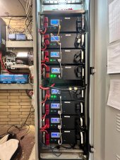
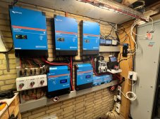
Hello forum members. I was hoping for some input on this. I picked up a 5kVA Victron inverter and the online manual specs 2 AWG from the AC1 output...holly cow. The manual also states a max capable current of 137A due to the 95A AC shore input, which I will not use. So, I will never see these numbers and was wondering of several things maybe someone would help me with:

1. What type of wire should this be, solid or stranded? There is nothing in the manual other than the word "cable." I assume this is stranded? (Oddly, there is nothing in the manual for the battery wire either, but I'm using 2/0 fine stranded).

2. I want to run the AC output wire in 30' of conduit, so sounds like even bigger wire of 0 AWG.... ahhhh... 3 x 0 AWG for 30' in conduit?!

3. The inverter will see no more than 35A continuous, with occasional additional inrush of an extra 28A when the 120VAC AC cylces. Couldn't I size the wire and breaker for this and be OK?

4. Lastly, the manual mentions a ferrule or stripped wire. Are there any feeling about this with the victron terminal blocks?

Any help would be greatly appreciated...thank you!


1691995191896.png

1691995277041.png

1691996755053.png
 

Attachments

  • 1691995245032.png
    1691995245032.png
    75.6 KB · Views: 8
I used solid core first to commission my system but later swapped to a higher gauge stranded wire on the advise of an electrician that inspected the system. His only remark regarding the difference between solid and stranded was that its absolutely necessary to use ferrules/sleeves crimped around the exposed wire that will be inserted into the terminal blocks if you will use stranded instead of solid wire. Not sure if that's useful info or not but thought i would share anyway :)
 
1: stranded. You won't be able to bend solid.
2: 1/0 wire, AC current, 30ft, 120v, 100a is 0.65% voltage drop.
3: breaker protects wire, so is OK. Make sure wire fits connection. Maybe a sub-panel from victron at max amps, then smaller wire. Just in case you want to add loads later.
 
Contrary to popular belief, solid cable is better at conducting DC power , HOWEVER, stranded is more suitable for mobile application and it is less likely to be damaged by vibrations
I believe you can compensate for the better conductivity of solid cable by simply increasing the gauge of the stranded wire you replace it with (which is what i did).

The solid was just too hard to work with for the short and bendy runs from the inverters to the maintenance panel (i have 3 x MP II 5000's - one per phase). So... i went with larger but much more flexible and easy to work with stranded wire.
Is it possible to post pics of your system?!
 
You're making a "service entrance" thus your brain should be thinking down several wire gauges from what you normally work with.

2 gauge us expensive.
 
Are you using AC IN? They are talking about grid assist that is why they are speccing such a large wire. You can also limit the maximum amperage out the inverter allows in software. So if you have a AC breaker rated for the size wire you will be using and specify maximum output in software on AC OUT 1 then you won't need anywhere near that size cable.
 
Are you using AC IN? They are talking about grid assist that is why they are speccing such a large wire. You can also limit the maximum amperage out the inverter allows in software. So if you have a AC breaker rated for the size wire you will be using and specify maximum output in software on AC OUT 1 then you won't need anywhere near that size cable.
As I've read on other posts and the fact I'm a newbie to the solar world, phase 1 is my baby step and will not use AC IN. Phase XX in the future, I would like to use the AC IN contingency even though the dream is to be completely self sufficient on solar and batteries. With that in mind, I was going to have an electrician run EMT sized to accomodate that expansion coupled with a new 200A service that would be installed also in the future. Your and DIYrich's answer makes me comfortable running the smaller wire and protect with appropriate breaker. Thank you!
 
Last edited:
Is it possible to post pics of your system?!
Sure! Here you go...

- 15kW capable 3 phase 25 amp Inverter System
- 12kW of PV attached to 2 x MPPT Pv Chargers (100A each)
- 40kWh of Pylontech compatible ESS (8 x 5.12 kWh battery modules)

System has been in service for over a year now...
 

Attachments

  • photo_2023-08-16_09-11-55.jpg
    photo_2023-08-16_09-11-55.jpg
    133 KB · Views: 52
  • photo_2023-08-16_09-12-00.jpg
    photo_2023-08-16_09-12-00.jpg
    192 KB · Views: 52
As I've read on other posts and the fact I'm a newbie to the solar world, phase 1 is my baby step and will not use AC IN. Phase XX in the future, I would like to use the AC IN contingency even though the dream is to be completely self sufficient on solar and batteries. With that in mind, I was going to have an electrician run EMT sized to accomodate that expansion coupled with a new 200A service that would be installed also in the future. Your and DIYrich's answer makes me comfortable running the smaller wire and protect with appropriate breaker. Thank you!
This is exactly what I'm doing right now. I had swapped out my old system for a pair of Victron 5kVA inverters and the old system was wired for 4awg wire with the appropriate breakers. I did size the conduit appropriately for future growth, but I changed the max current on the inverters for AC IN to be based on the 4awg wire. I primarily run on battery power until the SOC drops below a set threshold, then it switches over to AC IN until the SOC rises to 30% and then it switches back to battery power. It's been working great so far.
 
Sure! Here you go...

- 15kW capable 3 phase 25 amp Inverter System
- 12kW of PV attached to 2 x MPPT Pv Chargers (100A each)
- 40kWh of Pylontech compatible ESS (8 x 5.12 kWh battery modules)

System has been in service for over a year now...
Don't forget those inverters are 5,000KVA not 5,000W so you have 4,000W x 3 = 12,000W continuous at 25C, not 15,000W
 
Good catch! Yes, I counting on my single phase for 4kW.
The 4kw rating is based on an 80% power factor. Victron actually derates its output numbers assuming you’ll be running inductive loads which have a lower pf.

If you run a mix of inductive and resistive loads, you can get more then 4kw because the resistive loads have a higher pf.
 

Attachments

  • IMG_5665.png
    IMG_5665.png
    3 MB · Views: 9
Don't forget those inverters are 5,000KVA not 5,000W so you have 4,000W x 3 = 12,000W continuous at 25C, not 15,000W
Indeed... Nice catch... (y)

But as Adam mentions above, in practice they can actually do more than 4000W each depending on how they are used and the ambient temps etc. In pass through mode they certainly will handle 15kWh (for example when i use grid assist to charge my Tesla) and when I export energy from the battery at peak grid rates they will do around 13.5kWh quite happily for a couple of hours.
 
Passthrough relay in the 5kVA unit is capable of up to 95 amps so, in theory you can have the 95 amps pass-through from AC input to AC output plus the 41 amps from the 120vac inverter supplementing AC input for a total of 137 amps on AC output connector of inverter.

Realistically you will unlikely draw more than 50-60 amps from 120vac AC input. Just use the appropriate AC input breaker amperage.

I would use #6 AC input and output side wiring limiting use AC current to 60 amps.

Hopefully the 5kVA Multiplus has different terminal strips from 3kVA model which has the spring-loaded push-in AC connections that are prone to issues.

The 5kVA Quattro model has screw down set screws for AC in/out terminals.

Yes, the 5kVa models indeed have the screw down set screws and then that cable crimping support thing at the entry/exit of the housing as well.
 
Back
Top