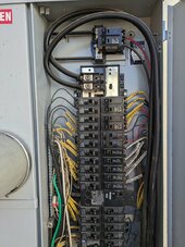
I should have asked this question before ordering an 18Kpv and three batteries. Can anyone report success installing feeder taps in a combination meter and main panel? I have Siemens MC series PV-ready panel, and while is does have cables between the meter and main breaker, and so far every electrician has passed on the job without even opening the panel(most saying too busy for a small job, one saying they just did not want the job).
The PV backfeed breaker at the top is connected to a SolarEdge that I plan to AC couple, so one possibility, if it would be code compliant, is to use it as my grid connection, knowing it is limited to 60A and replace the current main breaker with a 100A backfeed connected to the EG4 load side.
I'd rather not replace the meter/panel combo, but if that is what it will take...