diy solar

diy solar

AC Disconnect Installation Details

lapsmith

New Member
Joined
Apr 10, 2022
Messages
242
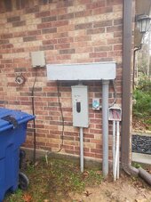
I am ready to install my AC disconnect. It has to be accessible to POCO personnel, so to me, that means outside. Here is a photo of where I plan to put it. I chose that location for ease of installation and because the line side connections are on the top of the switch. Is that spot in violation of any clearance or other requirements?
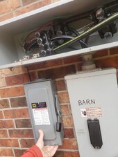
AC disconnect location.jpg

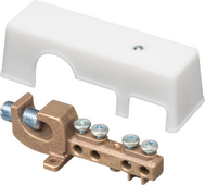
I also have a few wiring questions. L1 and L2 each have an available port on the multitap connector so I can use that. Neutral doesn't because that is where N-G is bonded.
  1. Is it legal to put two wires in one port of the multitap on the neutral line? I know you can't do that with circuit breakers unless they are specifically designed that way. If not, I will buy a 5 port multitap. They ain't cheap - are there any other options?
  2. Can I use PVC conduit to run L1, L2, N and G from the disconnect along the outside wall to where it will go inside the house? Also, should I transition to RMC going through the brick wall? Another option would be to feed the load side wires back up into the raceway and go all the way to the right where it could enter the house through the back of the raceway. It would be a cleaner installation, if allowed.
  3. The line side of the disconnect will be fed with #4 wire since that is the minimum size allowed for that particular multitap. Is it okay to run #6 wire from the load side of the disconnect to the inverter (Inverter rated at 48 amps)
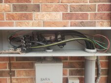
Here is another shot of the raceway containing the multitaps.

Raceway.jpg
 
Whether clearance requirements are met depends on what is below, chopped off in the pictures.

Not allowed to put two wires under one setscrew of the Polaris connector, I don't think.
I'm in the middle of a service upgrade, and what I did is I got 250 MCM connectors. I can feed 3/0 insulated wire through it, cut insulation in the middle, and use wire running out both sides.

My 200A main disconnect only has (for the moment) just a stub of wire to Polaris. Later it will have 3/0 wire running through Polaris to 200A sub-panel.

I hung a 100A disconnect (for PV) and a 125A sub-panel with 100A main breaker. I fed 2 awg wire from the disconnect, through the 200A main box and Polaris, back to the 125A sub-panel.

This uses fewer holes in Polaris.

I think you've got one tap left for L1/L2, but the N&G tap you've run out.
My 200A main has just one lug for each of L1/L2, but one large and four small lugs for N&G. I threaded wires through those small lugs too.

Sorry no photos yet.

My Polaris are OK for 6 awg to 250 MCM. But yours is 4 awg minimum?
I presume you will have OCP at the inverter?
I can't tell if disconnect is fused or unfused.
I'm not 100% certain on whether wire gauge change is allowed, or prohibited due to possible confusion. Works as well as 6 awg the whole way, just as matter of code.

For such a circuit protected at the far end, I read the rules were
1) in conduit
2) max 10'
3) At least 10% the amperage of upstream OCP.

What I did beyond that was I used 6 awg not 8 awg for ground of the 100A circuit, because 6 awg is size of ground required for 200A.
 
Whether clearance requirements are met depends on what is below, chopped off in the pictures.
Sorry about that. Here is the rest.

Wall at disconnect.jpg

I can feed 3/0 insulated wire through it, cut insulation in the middle, and use wire running out both sides.
Okay, that opens up some other possibilities. Thanks.

I think you've got one tap left for L1/L2, but the N&G tap you've run out.
Correct

My 200A main has just one lug for each of L1/L2, but one large and four small lugs for N&G. I threaded wires through those small lugs too.
Good idea. Unfortunately, my main panel only has one L1/L2 lug and can barely see the N bus bar behind all the wires.
My Polaris are OK for 6 awg to 250 MCM. But yours is 4 awg minimum?
Yes. The Neutral wire is 350MCM, but L1 and L2 are larger. I can't read the size, but my guess is 400. I can read the lable on the back of the L1 Polaris and the wire range is 350 to #4.

Question: If you feed a wire through the polaris and connect it to another one, you have to strip off all the insulation. Do you just use electrical tape to cover the exposed copper, or do you put the 2 polaris so they are touching?

I presume you will have OCP at the inverter?
I can't tell if disconnect is fused or unfused.
The AC disconnect is fused. It is on the opposite side of the wall from the inverter, but they seem to want it outside.

For such a circuit protected at the far end, I read the rules were
1) in conduit
2) max 10'
3) At least 10% the amperage of upstream OCP.
That is my understanding as well.
 
Clearance looks OK to me.
Breaker panels want something like 36" wide, 42" from wall (not necessarily centered?) give or take.
Recommendation in operation is to stand behind the door while operating handle. More of an issue for industrial size utility transformers (more fault current) and 3-phase (sustained arc-flash.)

I slipped 20' of 2 awg through Polaris so it was at middle. Marked the wire, then scored around in two places and sliced. I peeled off insulation in the middle of the wire. Insulation extends into Polaris insulation on both sides. Real clean.

If 3/0 hadn't slipped through (including insulation), I would have jammed up against other lugs, or insulated the bare stub. But with 250 MCM connectors and thin plastic THHN THWN insulation, it fit through.

I've played this game before (inside a disconnect, so I could have each output feed a pole of two 2P breakers), but I haven't had that inspected before. It doesn't look strange with Polaris, but turning the wire back right at the breaker (or fuse holder) does look "improvised."

Beyond that, I've used split bolts. Wrapped in rubber and vinyl. I feel better doing that with N and G, but I have done it with L1 and L2 (right at a breaker, so supported not contacting enclosure.)
 
Clearance looks OK to me.
Breaker panels want something like 36" wide, 42" from wall (not necessarily centered?) give or take.
Recommendation in operation is to stand behind the door while operating handle. More of an issue for industrial size utility transformers (more fault current) and 3-phase (sustained arc-flash.)
That's good. Yes, I remember we had a certain order of turning things on at work to minimize chances of arc flash.

I slipped 20' of 2 awg through Polaris so it was at middle. Marked the wire, then scored around in two places and sliced. I peeled off insulation in the middle of the wire. Insulation extends into Polaris insulation on both sides. Real clean.
Oh of course. I was thinking of my situation where the wire with insulation was too big to fit through the polaris. But still, that's a creative solution.

Beyond that, I've used split bolts. Wrapped in rubber and vinyl. I feel better doing that with N and G, but I have done it with L1 and L2 (right at a breaker, so supported not contacting enclosure.)
Do you know if split bolts can be used to join dissimilar sized wire (350MCM to #6)? If so, I could use your trick of trimming the insulation midway in the wire.
 
I think so. Data sheet talks about "run" and "tap". But I'm not certain; it isn't described in text.

I would avoid a situation where clamp bears down on large wire and small can fit to the side or corner without being compressed. Probably 350MCM strands can move to fill the space, unlike a solid conductor.


I've only used it for two of same size - tapping off 6 awg to connect a surge arrestor, and branching N and G inside a conduit tee.

It is handy to have something where wire can be slipped in from the side rather than over entire length. I have ground lugs like that, but not insulated splices. These split bolts fit the bill, but they have metal protrusions and need to be wrapped heavily. Would rather have hard plastic insulators. So I felt better using them for wires referenced to ground.
 
For the size split nut I need, the price was close to the Polaris, so I ordered the 5 port Polaris instead for an easier install. I will be away for a week, but will update you with the installation progress when I get back. Thanks a bunch Hedges!
 
I shop hard, and bought two brand new 4-port MCM 250-6 awg Polaris on eBay for 2x $25 = $50.
They fit side by side in my 200A main breaker only panel, one port lined up with breaker output.

I think some of the caps over holes, especially over setscrews, wriggle out on their own and jump to freedom. Careful not to lose yours, maybe set aside until done and wrap tape to retain.

I also got 32' (turned out to be 35') of 3/0 THHN-THWN for $125 ($60 + $65 shipping), plenty for my overhead service and meter to breaker. (will need more from main breaker to 200A sub panel.)

Inspection is this morning.

Edit: Inspection failed, but not for use of Polaris or feeding through lugs.

 
Last edited:
I shop hard, and bought two brand new 4-port MCM 250-6 awg Polaris on eBay for 2x $25 = $50.
They fit side by side in my 200A main breaker only panel, one port lined up with breaker output.

I think some of the caps over holes, especially over setscrews, wriggle out on their own and jump to freedom. Careful not to lose yours, maybe set aside until done and wrap tape to retain.

I also got 32' (turned out to be 35') of 3/0 THHN-THWN for $125 ($60 + $65 shipping), plenty for my overhead service and meter to breaker. (will need more from main breaker to 200A sub panel.)

Inspection is this morning.

Edit: Inspection failed, but not for use of Polaris or feeding through lugs.

That's a great price for the Polaris. I did some checking as well, but couldn't find anything cheaper. Thanks for the tip on not losing the caps. I'm usually good at that kind of stuff.

Sorry to hear about the inspection. Is it going to be hard to fix?
 
Not too hard. I was worried until I figured it out.

Biggest issue was location of meter, 87" above grade where 75" is per Greenbook.
Had been a clean install with meter above breaker, 12" of 3/0 almost straight through.
My solution is meter to left of breaker. Offset conduit nipple because knockouts don't line up, gasketed hubs. Going to be fun putting four 90 degree bends in 3/0 to go down, over, up, back over, down. The box layout even offends my poorly developed OCD.

Secure 2" service riser pipe within 3' of box and at 3' intervals. (was only one at top.) Now that it runs over a shutter, will use longer lag screws as well. Glad I re-read the notice to post this, I previously missed the 3- intervals. One extra clamp can still do it, if top clamp no more than 6' above box, but second clamp will have to go through shutter louvers rather than bottom frame.

Others: I used 6 awg ground to two rods and water pipe. Because 6 awg is ground for 200A circuits. Turns out, the ground conductor to water pipe must be 4 awg. No reason I can see based on ohms law and voltage drop. Could have been separate wire, using up my last empty lug, but I want that for the coming 200A sub-panel. So I got 50' coil of 4 awg.

Existing water heater has 10 awg bond cold/hot/gas. Replace with 4 awg.

Inter-system ground bar required outside under breaker box. (all communications presently goes into basement and ground there. OK, bought a couple bronze ones on eBay, rather than zinc or aluminum from home improvement stores. Lay-in lug so can mount after the fact.

He did note my ground rod clamps were approved for direct burial. Some have rustable screw, OK for above ground pipes.

Must install surge protector (maybe a local requirement?) Thought I could get a QO 50kA with pigtail, but only see plug-on neutral. Some options have flying leads, require separate breaker, and mount on a knock-out. I'm avoiding extra stuff popping out of the boxes; they have all conduit hidden into basement except the overhead utility riser and now the offset nipple. Bought 5x 22kA QO with pigtail on eBay for $225. Will use two for my 100A and 200A sub panel. Might add one to another property. I think I will DIY another upstream at main breaker + Polaris, high amperage and higher voltage. After inspector is gone. Will add fuses in-line.

Something along these lines, whatever I bought for 600VDC PV strings:


Water pipe under box has to go. It is OK to lean up against a ground wire, but not a water pipe. Will unthread into house, add shut-off. Later run inside basement, pop out where it was before to the side of box.

Working clearance around panel. Could have moved faucet to where pipe comes out of wall but would have had to remove bush that has grown for 60 years. Will just chop bush vertically to be clear of panel, have 30" space to the left of that. Faucet to right like before, just no pipe under panel.

I would guess he gets annoyed seeing the same violations over an over. Usually by the uninitiated, but I'm someone who ought to be more up on this. It has been 20 years since I touched a service entrance box needing inspection, and 40 years since I installed one. I mostly work by understanding, not by reading all the codes.

I had planned for Polaris to support one more 200A circuit. Was going to have to do something for Neutral. But no room in conduit, would have to add another ugly external one. Instead, think I'll daisy chain off the 200A panel I'm adding. (thinking 120% rule etc, if I tapped before sub-panel breaker, would have issue of 200A service disconnect + 100A fused disconnect to PV, through 3/0 into two 200A breakers. Could use 4/0.) Might put the 200A circuit downstream of 200A panel. I did buy a QO tap. There will be one 2" conduit feeding the panel from service disconnect. I think I'll try for 2.5" not 2" feeding out, room for more wires.
 
Biggest issue was location of meter, 87" above grade where 75" is per Greenbook.
Can you just add more dirt, assuming it is outside?
Secure 2" service riser pipe within 3' of box and at 3' intervals. (was only one at top.) Now that it runs over a shutter, will use longer lag screws as well. Glad I re-read the notice to post this, I previously missed the 3- intervals. One extra clamp can still do it, if top clamp no more than 6' above box, but second clamp will have to go through shutter louvers rather than bottom frame.
I thought it was only 1 inch and smaller that needed support every 3 feet. When I ran my 1 inch PVC conduit, I did it at 3 feet. Glad I did because any more and it would have had some sag.
Others: I used 6 awg ground to two rods and water pipe. Because 6 awg is ground for 200A circuits. Turns out, the ground conductor to water pipe must be 4 awg. No reason I can see based on ohms law and voltage drop. Could have been separate wire, using up my last empty lug, but I want that for the coming 200A sub-panel. So I got 50' coil of 4 awg.
Yeah, doesn't make sense to me either.
Inter-system ground bar required outside under breaker box.
What is an inter system ground bar?
Water pipe under box has to go. It is OK to lean up against a ground wire, but not a water pipe.
Another mystery why.
would have had to remove bush that has grown for 60 years. Will just chop bush vertically to be clear of panel
That's an easy one!
I mostly work by understanding, not by reading all the codes.
Well, you impress me with your knowledge of the codes.
 
Can you just add more dirt, assuming it is outside?

I briefly considered a platform. Would have to be large enough.

I thought it was only 1 inch and smaller that needed support every 3 feet. When I ran my 1 inch PVC conduit, I did it at 3 feet. Glad I did because any more and it would have had some sag.

1" PVC would not make a good riser to weather head for utility drop.
This requirement is for a riser, not just for conduit.

In a similar vein, I put in vinyl gutters and they really sag. Need a support every rafter. One piece metal would be so much nicer.

Yeah, doesn't make sense to me either.

Somebody here said it dates from when water pipe was used as the ground. But still makes no sense. No benefit seen by the code writers to change it.

What is an inter system ground bar?

That's what I said. It is a ground bar connected to the grounding electrode conductor, located right below the service entrance panel. For all the telecom etc. to ground to. Something like this:

1705815627624.png

Another mystery why.

Ideas are codified as words, after which only what the words say matters.
He noted my brick trim stuck out a fraction of an inch, but said he would let that go.

That's an easy one!

He suggested removing the bush. Instead I'll spend a few bucks and hours re-routing the water pipe.

The contradictory thing is city zoning wants a meter, if put on front of house, to be obscured from view. Like with a potted plant.
Maybe I can trim the main bush to block view but comply with setbacks from panel.

New meter & main breaker goes in the open space. Then old meter shown will be replaced with 200A sub-panel.


Well, you impress me with your knowledge of the codes.

I've dabbled in the field for decades, but that means I'm out of date.
I've picked up some safety training at my day job, like arc flash. Also AED. Good thing I did QEW training the day before I shocked myself!

 
That's what I said. It is a ground bar connected to the grounding electrode conductor, located right below the service entrance panel. For all the telecom etc. to ground to. Something like this:
Good to know, thanks.
The contradictory thing is city zoning wants a meter, if put on front of house, to be obscured from view. Like with a potted plant.
It's always something.
I've dabbled in the field for decades, but that means I'm out of date.
I've picked up some safety training at my day job, like arc flash. Also AED. Good thing I did QEW training the day before I shocked myself!
You're not the only one. I didn't shock myself, but this morning I did something stupid. I was trying to see why my battery won't talk to the inverter, it was telling me there was a problem with the battery connections. I fiddled around (with power on) thinking the battery wouldn't be hot if there was an error. My screwdriver proved otherwise and didn't like it with a bunch of amps going across it. It blew the 30 amp generator breaker that was feeding the inverter and tripped or fried something inside the inverter. Now when I power it up, I get no PV input. Everything else seems to be working on power up.

I started to disassemble the inverter to look for a fuse (don't see any), but they built the thing like it would never have to be repaired. I guess they figure it will be thrown out. Another reason why they can sell it so cheap, I guess. There is no smell of magic smoke, so I'm not sure what tripped.

Strange why a short on the battery side of the inverter would trip the grid circuit breaker and also do something to the DC input.
 
If battery was supplying part load and generator feeding part, then taking one offline could do something. But fast tripping a breaker takes 5x rated current.
Since inverter is a switcher, it could do things wrong with FET timing. Would think shoot-through two FETs both on in series would be hardware interlocked.
Surges can do things. I connected one PV inverter backwards to PV input of another (thought I was transferring PV array). Blew fuses. A comms card was dead after that, don't know if this killed it.

I can be pretty brain dead. I said the ground electrode conductor was 6 awg because that's what I thought I bought years ago for 200A service. Label had come off. Inspector said to use 4 awg. I bought a coil, removed the old, opened new package and realized they were same size. I had bought 4 awg years before.
 
I'm 99% sure the battery wasn't supplying any load since the inverter was reporting a wiring error. The inverter was strictly supplying loads through the breaker on the service panel. I partially disassembled the inverter and didn't see any fuses. Nor did I smell any strong smell of magic smoke, but there could have been something very faint. What do you mean by:
Would think shoot-through two FETs both on in series would be hardware interlocked.

I buy stuff that I think I need then realize I know have two of them. Oh, don't you love when that happens?
 
Back
Top