diy solar

diy solar

Alligator Clip Vs. Cable Lug Vs. Anderson connector

Easyyokefilms

New Member
Joined
Aug 5, 2023
Messages
38
Location
Lagos
Hello, I have two different sets of batteries. Set 1 - Two 100ah Redodo 12v batteries paralleled together Set 2 - Two 100ah Litime 12v batteries paralleled together. I could not parallel all 4 together because they are from different manufacturers and I also bought them at different times. However, I have only one inverter(Renogy 12 1000w).

So here in lies my issue, the inverter comes with a 25mm cable with cable lugs at both end of the cable. However, when my battery set 1 is low, I intend to then switch the inverter from Battery set 1 to Battery Set 2. Using an Alligator clip at the end of the inverter cable seem to be the most convinient as I can easily just switch between the two batteries set but I read somewhere that alligator clips have resistance that causes power loss(I dont know if this is true). Using the cable lug that came with the inverter will be too stressful for me as I will have to continually screw and unscrew each time I need to switch the inverter from Battery Set 1 to Battery Set 2. What would be the most professional and easiest route you will take. I am still leaning towards an alligator clip, but looks like using an Anderson connector is also a good option. Which would you advice I go for that would be the easiest and safest for switching my inverter between the two sets of batteries? My load is maximum 700w so I am not using very heavy loads.
 
None of those options are good, only less bad.

You can parallel the lithium batteries.
 
None of those options are good, only less bad.

You can parallel the lithium batteries.

What he said :

See here :


Just make sure they are at the same Voltage when connected.

Alligator clip is a terrible idea, Anderson connectors go up to 350 Amps, ring terminals is best.

 
I would wire all four batteries in parallel to a busbar, and then a larger wire to the inverter and not worry about plugging and unplugging batteries throughout the day. For me, There is a risk with plugging and unplugging and overtime, something would happen.

On a portable milk crate setup I have, I occasionally swap inverters, so I have an Anderson plug to easily switch inverters.
My load is maximum 700w so I am not using very heavy loads.
I consider this a respectable load for 12 volts. This could be around 80 amps with low votlage cutoff and dc conversion losses.

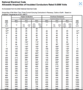
Based off this chart, I'd wire this with 2 AWG copper THHN from Home Depot and connect the batteries with a 2 AWG to #10 lug.
1714483205107.png
 
If you are really set on wanting to switch from battery bank 1 to battery bank 2 I would suggest using a DC breaker on each battery output after a fuse. From each breaker you can go to your inverter or to a bus bar than inverter. Turn off one and turn on the other. Try to avoid ever switching under load.
 
I would wire all four batteries in parallel to a busbar, and then a larger wire to the inverter and not worry about plugging and unplugging batteries throughout the day. For me, There is a risk with plugging and unplugging and overtime, something would happen.

On a portable milk crate setup I have, I occasionally swap inverters, so I have an Anderson plug to easily switch inverters.

I consider this a respectable load for 12 volts. This could be around 80 amps with low votlage cutoff and dc conversion losses.

Based off this chart, I'd wire this with 2 AWG copper THHN from Home Depot and connect the batteries with a 2 AWG to #10 lug.
View attachment 212422
But I heard you shouldn’t parralel batteries from different manufacturers and batteries bought at different times. You mean I could ignore this rule and just parallel all 4 without any consequences?
Also the Litime is the mini(Pouch cells), while the Redodo is the normal Prismatic cells
 
Last edited:
If you are really set on wanting to switch from battery bank 1 to battery bank 2 I would suggest using a DC breaker on each battery output after a fuse. From each breaker you can go to your inverter or to a bus bar than inverter. Turn off one and turn on the other. Try to avoid ever switching under load.
I am really not set on wanting to switch battery as it is even stressful for me. But there is this rule of not paralleling batteries made from different manufacturers and bought at different times. The Litime is atleast 6months older than the redodo. If I parallel all of them, will I be ok. I have seen many literature saying not to parallel different manufacturers. Also the Litime is the mini(Pouch cells), while the Redodo is the normal Prismatic cells
 
You may be able to parallel all 4 together.

Different cell types should not be paralleled. In theory it works, in practice you need to check that the charge curves match. You also have to start by charging all 4 batteries fully and checking that they are within 0.02v of each other.

That means fully charge then let rest a few hours and meassure the voltage.

If both of those are true you can parallel all 4. In practice if it were me I would keep they separate.

If they are stationary then you can just get a 2 position battery disconnect switch that is ON-OFF-ON. You would want that sequence so you never connect the battery sets in parallel while one set is full and the other is empty. The flash of instantaneous current could easily make the wires red hot.

Anderson connectors like you say would be another way to do it.

For the wire see the post below. You want to use welding wire not THHN. THHN is wire used in household walls or other places where it is never intended to flex or bend. Bend it back and forth enough and it will break strands internally and you will get hot spots from the added resistance. The NEC code is intended for that type cable, but welding wire has a higher heat rating. And the finer wire won't loose as many watts from heating.


lemme say it once more ... THHN is a terrible idea for your application.

For 2 batteries in parallel use MRBF fuses and holders on the battery posts. If your batteries are 100amp use 125amp fuses.


It is worth buying real anderson connectors for your application. Not like you will need a ton of them.


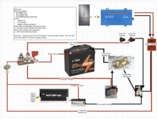
Attached is the diagram of my cpap backup battery. For you, just do the two batteries in parallel.
 

Attachments

  • cpap backup.png
    cpap backup.png
    400.9 KB · Views: 1
Last edited:
I don't like Anderson connectors because over time they loosen up and run hot.

Flexable cables.
I once had to wire some MCCs with a marine 313MCM flex that was wonderful stuff.
But it was a weird cable size and I was using 350MCM lugs ( because i was told to do that ) and I used a pin crimper.
I was happy with how it turned out but I want to warn you that sometimes a cable rated at say... 4/0 will not fit a regular compression lug.
you might need one for that specific kind of cable with a flared barrel or a goofy size.

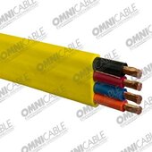
I did a job on a scrap metal crane that used this type of festoon but the wire size was #4.
I liked it a lot and I wired up a bank of lead acid batteries at camp with the conductors in Parallel to a buss bar.
Everything was exactly the same and the cable was always cool running and connections always cool to the touch.
I'm not saying this was right!
But it was right for me ( free scrap cable )
And it worked very well..

1714488678908.jpeg
 
I am really not set on wanting to switch battery as it is even stressful for me. But there is this rule of not paralleling batteries made from different manufacturers and bought at different times. The Litime is atleast 6months older than the redodo. If I parallel all of them, will I be ok. I have seen many literature saying not to parallel different manufacturers. Also the Litime is the mini(Pouch cells), while the Redodo is the normal Prismatic cells
OK a bit to unpack:
1) Never Ever mix different Chemistries into a parallel bank. Use ONLY the Same Chemistry. LFP exists in prismatic, pouch & cylindrical formats.
2) Age is NOT a major concern (unlike Lead Acid & Variants). Each Battery Pack is "Independant" with its own BMS.
3) You CAN mix different capacity battery packs into a parallel system without issues BUT this does require adjustments on he main charging profile to ensure using a "Moderate Profile" which remains within the Working Voltage Range. Additionally, the calculations of EndAmps/Tailcurrent for transition from Bulk/Absorb to Float must be correct.
4) MOST IMPORTANT !!! Every battery Pack will have its Max Charge Input C-Rate - and you cannot exceed that. This is not as bad as it seems on first blush . When packs are in Parallel the take charge in Proprtion to their AH as well
5) Technically any "Battery Bank" can have as many Packs as you want BUT management of that gets more & more complex. There comes a point where your Selected Voltage for your system because cumbersome & time to leap up to the next Voltage Level.

I've run a Battery Bank with 1x100AH, 2x175AH, 3x280AH in one bank and NEVER a problem. A moderate Charge Profile and respecting the EndAmps, never had troubles transitioning to Float when amps taken dropped to the correct point. As the bank drops, the batteries stay pretty level but as the lower capacity packs et lower, they actually discharge lower Amps than the higher capacity packs show shoulder more of the load. It is actually quite Proportional to their capacities. This can be easily observed while charging & discharging provided your BMS' can provide that detail level (needs a SmartBMS with good software to monitor the pack & cell levels. An A-Typical view of how this worked is as follows:
During charge: 3x280's would take 28A ea, the 175's took around 17A while the 100 would take 10A (NOTE this is a simplified example) but in essence it is how it plays out. Because I can change anywhere from 10A up to 275A the numbers vary with it. Also depending on the state of SOC in each pack, the lower ones will take more amps initially till they "catch up" to the big boys & then settle to proportionate mode.

Hope it Helps, Good Luck.

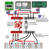
Here is one of my generic diagrams that show how to parallel packs and keep everything in good order & safe.
Parallel System-setup PNG.png
 
Hello, I have two different sets of batteries. Set 1 - Two 100ah Redodo 12v batteries paralleled together Set 2 - Two 100ah Litime 12v batteries paralleled together. I could not parallel all 4 together because they are from different manufacturers and I also bought them at different times. However, I have only one inverter(Renogy 12 1000w).

So here in lies my issue, the inverter comes with a 25mm cable with cable lugs at both end of the cable. However, when my battery set 1 is low, I intend to then switch the inverter from Battery set 1 to Battery Set 2. Using an Alligator clip at the end of the inverter cable seem to be the most convinient as I can easily just switch between the two batteries set but I read somewhere that alligator clips have resistance that causes power loss(I dont know if this is true). Using the cable lug that came with the inverter will be too stressful for me as I will have to continually screw and unscrew each time I need to switch the inverter from Battery Set 1 to Battery Set 2. What would be the most professional and easiest route you will take. I am still leaning towards an alligator clip, but looks like using an Anderson connector is also a good option. Which would you advice I go for that would be the easiest and safest for switching my inverter between the two sets of batteries? My load is maximum 700w so I am not using very heavy loads.


One more tidbit here - there is a very high chance that the cables that came with the inverter are copper clad aluminum .... in other words crap... They will work, but it is not great at its job.

You should clip one end off of each cable and look at it under light and a magnifier and see if the ends are shiny copper or aluminum. If it is aluminum throw them in the bin or recycle bucket. Mixed metal recycle generally pays a few pennies a pound so isn't worth a trip for just it.

One inverter I got had cables included with it. One marked in Chinese and the other not marked. Both were CCA and using them just to test things out for a few hours the ends turned black.
 
  • Like
Reactions: Bop
OK a bit to unpack:
1) Never Ever mix different Chemistries into a parallel bank. Use ONLY the Same Chemistry. LFP exists in prismatic, pouch & cylindrical formats.
2) Age is NOT a major concern (unlike Lead Acid & Variants). Each Battery Pack is "Independant" with its own BMS.
3) You CAN mix different capacity battery packs into a parallel system without issues BUT this does require adjustments on he main charging profile to ensure using a "Moderate Profile" which remains within the Working Voltage Range. Additionally, the calculations of EndAmps/Tailcurrent for transition from Bulk/Absorb to Float must be correct.
4) MOST IMPORTANT !!! Every battery Pack will have its Max Charge Input C-Rate - and you cannot exceed that. This is not as bad as it seems on first blush . When packs are in Parallel the take charge in Proprtion to their AH as well
5) Technically any "Battery Bank" can have as many Packs as you want BUT management of that gets more & more complex. There comes a point where your Selected Voltage for your system because cumbersome & time to leap up to the next Voltage Level.

I've run a Battery Bank with 1x100AH, 2x175AH, 3x280AH in one bank and NEVER a problem. A moderate Charge Profile and respecting the EndAmps, never had troubles transitioning to Float when amps taken dropped to the correct point. As the bank drops, the batteries stay pretty level but as the lower capacity packs et lower, they actually discharge lower Amps than the higher capacity packs show shoulder more of the load. It is actually quite Proportional to their capacities. This can be easily observed while charging & discharging provided your BMS' can provide that detail level (needs a SmartBMS with good software to monitor the pack & cell levels. An A-Typical view of how this worked is as follows:
During charge: 3x280's would take 28A ea, the 175's took around 17A while the 100 would take 10A (NOTE this is a simplified example) but in essence it is how it plays out. Because I can change anywhere from 10A up to 275A the numbers vary with it. Also depending on the state of SOC in each pack, the lower ones will take more amps initially till they "catch up" to the big boys & then settle to proportionate mode.

Hope it Helps, Good Luck.

Here is one of my generic diagrams that show how to parallel packs and keep everything in good order & safe.
View attachment 212450


All great info -


To the OP, this level of detail is why I would just use a disconnect to keep things separate.
 
T
You may be able to parallel all 4 together.

Different cell types should not be paralleled. In theory it works, in practice you need to check that the charge curves match. You also have to start by charging all 4 batteries fully and checking that they are within 0.02v of each other.

That means fully charge then let rest a few hours and meassure the voltage.

If both of those are true you can parallel all 4. In practice if it were me I would keep they separate.

If they are stationary then you can just get a 2 position battery disconnect switch that is ON-OFF-ON. You would want that sequence so you never connect the battery sets in parallel while one set is full and the other is empty. The flash of instantaneous current could easily make the wires red hot.

Anderson connectors like you say would be another way to do it.

For the wire see the post below. You want to use welding wire not THHN. THHN is wire used in household walls or other places where it is never intended to flex or bend. Bend it back and forth enough and it will break strands internally and you will get hot spots from the added resistance. The NEC code is intended for that type cable, but welding wire has a higher heat rating. And the finer wire won't loose as many watts from heating.


lemme say it once more ... THHN is a terrible idea for your application.

For 2 batteries in parallel use MRBF fuses and holders on the battery posts. If your batteries are 100amp use 125amp fuses.


It is worth buying real anderson connectors for your application. Not like you will need a ton of them.


Attached is the diagram of my cpap backup battery. For you, just do the two batteries in parallel.
Thanks a lot for your response. I also learnt a new thing about those wire types
 
OK a bit to unpack:
1) Never Ever mix different Chemistries into a parallel bank. Use ONLY the Same Chemistry. LFP exists in prismatic, pouch & cylindrical formats.
2) Age is NOT a major concern (unlike Lead Acid & Variants). Each Battery Pack is "Independant" with its own BMS.
3) You CAN mix different capacity battery packs into a parallel system without issues BUT this does require adjustments on he main charging profile to ensure using a "Moderate Profile" which remains within the Working Voltage Range. Additionally, the calculations of EndAmps/Tailcurrent for transition from Bulk/Absorb to Float must be correct.
4) MOST IMPORTANT !!! Every battery Pack will have its Max Charge Input C-Rate - and you cannot exceed that. This is not as bad as it seems on first blush . When packs are in Parallel the take charge in Proprtion to their AH as well
5) Technically any "Battery Bank" can have as many Packs as you want BUT management of that gets more & more complex. There comes a point where your Selected Voltage for your system because cumbersome & time to leap up to the next Voltage Level.

I've run a Battery Bank with 1x100AH, 2x175AH, 3x280AH in one bank and NEVER a problem. A moderate Charge Profile and respecting the EndAmps, never had troubles transitioning to Float when amps taken dropped to the correct point. As the bank drops, the batteries stay pretty level but as the lower capacity packs et lower, they actually discharge lower Amps than the higher capacity packs show shoulder more of the load. It is actually quite Proportional to their capacities. This can be easily observed while charging & discharging provided your BMS' can provide that detail level (needs a SmartBMS with good software to monitor the pack & cell levels. An A-Typical view of how this worked is as follows:
During charge: 3x280's would take 28A ea, the 175's took around 17A while the 100 would take 10A (NOTE this is a simplified example) but in essence it is how it plays out. Because I can change anywhere from 10A up to 275A the numbers vary with it. Also depending on the state of SOC in each pack, the lower ones will take more amps initially till they "catch up" to the big boys & then settle to proportionate mode.

Hope it Helps, Good Luck.

Here is one of my generic diagrams that show how to parallel packs and keep everything in good order & safe.
View attachment 212450
Thanks so much for the response. I got your explanation perfectly and thank you for the diagram, it makes the explanation even clearer
 
OK a bit to unpack:
1) Never Ever mix different Chemistries into a parallel bank. Use ONLY the Same Chemistry. LFP exists in prismatic, pouch & cylindrical formats.
2) Age is NOT a major concern (unlike Lead Acid & Variants). Each Battery Pack is "Independant" with its own BMS.
3) You CAN mix different capacity battery packs into a parallel system without issues BUT this does require adjustments on he main charging profile to ensure using a "Moderate Profile" which remains within the Working Voltage Range. Additionally, the calculations of EndAmps/Tailcurrent for transition from Bulk/Absorb to Float must be correct.
4) MOST IMPORTANT !!! Every battery Pack will have its Max Charge Input C-Rate - and you cannot exceed that. This is not as bad as it seems on first blush . When packs are in Parallel the take charge in Proprtion to their AH as well
5) Technically any "Battery Bank" can have as many Packs as you want BUT management of that gets more & more complex. There comes a point where your Selected Voltage for your system because cumbersome & time to leap up to the next Voltage Level.

I've run a Battery Bank with 1x100AH, 2x175AH, 3x280AH in one bank and NEVER a problem. A moderate Charge Profile and respecting the EndAmps, never had troubles transitioning to Float when amps taken dropped to the correct point. As the bank drops, the batteries stay pretty level but as the lower capacity packs et lower, they actually discharge lower Amps than the higher capacity packs show shoulder more of the load. It is actually quite Proportional to their capacities. This can be easily observed while charging & discharging provided your BMS' can provide that detail level (needs a SmartBMS with good software to monitor the pack & cell levels. An A-Typical view of how this worked is as follows:
During charge: 3x280's would take 28A ea, the 175's took around 17A while the 100 would take 10A (NOTE this is a simplified example) but in essence it is how it plays out. Because I can change anywhere from 10A up to 275A the numbers vary with it. Also depending on the state of SOC in each pack, the lower ones will take more amps initially till they "catch up" to the big boys & then settle to proportionate mode.

Hope it Helps, Good Luck.

Here is one of my generic diagrams that show how to parallel packs and keep everything in good order & safe.
View attachment 212450
One more thing, why did you decide to use two sets of busbars instead of just one set in the diagram
 
One more thing, why did you decide to use two sets of busbars instead of just one set in the diagram
Simplicity. 12V batteries, most common busbar being 4 bolt... rackmounts often use long strip busbars and many other formats out there. All depends on application and the requirements.
 
Be careful about the bus bars you buy from amazon. A lot of the cheaper ones are listed as 300amp but in no way will carry that much amperage.

To verify - if the listing says they are copper, file a corner off the bar deep enough to get through the plating and verify it is copper. If it says it is brass you don't need to do this.

Measure the physical diminsions on the end of the bar in millimeters. Multiplye length times width to get area. For copper multiply by 4.92 and for brass multiply by 1.96. This is the amperage your bar will carry.

Next examine how the studs are installed. Are they tight? Are they studs screwed into threaded hole? Are they bolts tight against the back of the bar? Best is bolts tight against the back of the bar, worst is bolts through a non-threaded hole and only holds from the plastic around it.

The current passes through the lug to bar interface, not the stud so it doesn't matter what the stud is made from.

When putting lugs on a bus bar - 1 lug per stud, don't stack unless you have no choice - much better to buy a bus bar with more lugs on it than to stack. The correct order is bar - lug - washer - lock washer - nut. The lock washer can be combined in with the nut depending on style.
 
One more tidbit here - there is a very high chance that the cables that came with the inverter are copper clad aluminum .... in other words crap... They will work, but it is not great at its job.

You should clip one end off of each cable and look at it under light and a magnifier and see if the ends are shiny copper or aluminum. If it is aluminum throw them in the bin or recycle bucket. Mixed metal recycle generally pays a few pennies a pound so isn't worth a trip for just it.

One inverter I got had cables included with it. One marked in Chinese and the other not marked. Both were CCA and using them just to test things out for a few hours the ends turned black.
It isn't always easy to tell them apart visually, but the good old cigarette lighter test shows if you have CCA cables or not...
Easiest way (and doesn't need cutting off any terminals) is just strip back a bit of the insulation (just slit it and 'dig out' a single strand), and cut that single strand of the wire, and bend it out away from the terminal... then heat it up with a lighter- copper will stay stiff and mildly discolour, CAA will bend and go 'floppy'...
(only a minute and a half long)
Best thing is if it is a good copper cable, just put some heatshrink over the slit and you can still use the cable... no need for a new terminal to be fitted...
 
Back
Top