diy solar

diy solar

Connect 2 wire 220v to panel for 110v circuits in a camper!

timferra

New Member
Joined
Apr 5, 2020
Messages
30
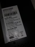
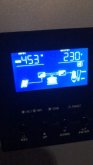
I have the following inverter. 5kva hybrid 48vpure sine wave inverter with charge controller.

In my camper, the system is off grid. Using solar panels (2-315w) and a 4-100ah 12v batteries ran in series. No other power source, as Colorado is always sunny. The inverter does have an AC input to plug
into a outlet if I wanted to charge the batteries that way, but it is not a necessity to me.

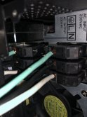
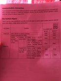
It’s the 5kva, 48v. Model. It has 3 wires as the AC output of 230v. It lists the 3 outputs as ground, leg or hot, and neutral. But I tested the wires. And the hot is 117v, and the neutral is 113v. Testing that both are a 110v hot?
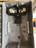
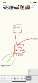
I am trying to run this into a electrical panel, and run my trailer camper with receptacles At 110v. Maybe just 2 breakers is all I need to run a few lights, 5 outlets,

I am Trying to figure out if the neutral is actually a hot, how do I hook it up? Do I ru. The 2 hits into separate circuit breakers, connect all the grounds to the left bus bar, and ground it to the chassis. And not use a neutral? If it doesn’t actually have a neutral output, does that mean it has an internal Neutral, and I should bond my neutral to ground? Or should I connect all the neutrals on the right bar, and then run it to the AC input neutral or hot, and make a loop so any overpower returns to the inverter? I am really confused by the neutral situation. I don’t want to screw anything up and fry myself or the system. Any advice would be greatly appreciated in advance!!

the manual doesn’t say anything about this, and I’m having trouble finding anything online.
Help!!!! ?

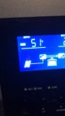
it does have a option in the display to have internal neutral ground bond enables or disabled.
 
Lets start with the internal neutral ground bond.

Neutral should always be bonded to ground *at the source*. That puts the inverter in an interesting role. When it is providing power via the shore power plug, it should *not* bond neutral to ground. When it is providing power via the battery, it is the AC Source and it *should* bond neutral to ground. I do not know what your inverter does. A good inverter will auto-magicly change the neutral bond based on whether it is connected to shore power or not.
and the neutral is 113v
Is that measured from Neutral to ground? If so then try enabling bonding to ground and see shat it does. My guess is the AC is currently 'floating' and once you bond to ground things will look a lot different.
 
Lets start with the internal neutral ground bond.

Neutral should always be bonded to ground *at the source*. That puts the inverter in an interesting role. When it is providing power via the shore power plug, it should *not* bond neutral to ground. When it is providing power via the battery, it is the AC Source and it *should* bond neutral to ground. I do not know what your inverter does. A good inverter will auto-magicly change the neutral bond based on whether it is connected to shore power or not.

Is that measured from Neutral to ground? If so then try enabling bonding to ground and see shat it does. My guess is the AC is currently 'floating' and once you bond to ground things will look a lot different.

hey! Thanks for the response! Here is the setting.As default it is not connected (38 in picture) , that measurement is with it not bomded neutral to ground should I change it to-enable bond. Then Test the wires?

1586706984436.png
 
Last edited:
Interesting. It requires an external box to actually do the bonding. Doing the setting won't change anything. However, when the external grounding box is set up, it works as it should (bond to ground when on battery)

You have a choice. You can either just manually bond neutral to ground/chassies or set up the external control. For an RV, since the whole vehicle is sitting on rubber tiers, I am not sure the 'switching' is that important. I would be tempted to tie the neutral and ground wires together....

Okay! I really appreciate the assistance with this,

just to clarify: from that point forward in the panel connect: neutral to right bar (even with it carrying voltage). ground to left bar, and a ground to the frame? and the hot to the hot lug? Is this correct?
The hook up breakers to receptacles throughout the camper? It has no existing electrical, I took it all out.

Man this site is really supportive, I really appreciate it! ?
 
Just to be clear: The *correct* way would be to hook up an external relay that dynamically creates the bond when the AC source is the battery. However, as I said, in a van that is sitting on rubber tires there is no earth ground so the dynamic bonding is probably less critical. However, if you do manually bond the nuetral wire to the ground wire at the inverter, you will be 'out of code' if you ever plug in to shore power.

Assuming you are not going to set up a relay and 'just' manually connect them together there are two different things going on:
1) Bonding the Neutral wire to the ground wire that runs through all of the AC distribution.
2) Bonding the Neutral/ground wire to Chassis.
 
What would you think is best? I’m very new to this! Any advice
Would Be a great!
 
The bonding between the Neutral wire and ground wire should be done at the inverter. That one is simple.

Bonding the Neutral/Ground to chassis should be done at one place, preferably at the inverter. However, that may get tricky in a van.
As an example: if you have a metal box for a 120V plug that is mounted on metal of the chassis, it will likely end up being connecting the ground wire to chaises via the ground of plug. If you also have the ground wire bonded to chassis at the inverter, then there are two places that ground is connected to chassis. This creates a ground loop that may (or may not) cause you problems.

The ideal situation would be to use plastic junction boxes and ensure that the AC ground wire never connects to chassis except at the inverter.
 
I have this plastic box laying around! How do I ground it at the inverter? Just take the inverter ground output and connect it to the chassis? Or mount the metal frame of Inverter to the chassis?
And then bond the neutral and ground in the plastic box?
 

Attachments

  • 2DB1A3BC-65AB-4627-AEE0-684867AC3343.jpeg
    2DB1A3BC-65AB-4627-AEE0-684867AC3343.jpeg
    98.1 KB · Views: 5
BTW: I do not like they way your inverter handles the dynamic ground wire bonding. (It feels like they punted the problem to the consumer) What is the exact make/model of your inverter? I would like to look at the manual to understand the signals for the external bonding control.

BTW2: My description of bonding AC ground to chassis is correct regardless of whether the Neutral-Ground wire bonding is dynamic.
 

Attachments

  • 0AA3507B-F5F2-4C7A-8387-A256274AC30D.jpeg
    0AA3507B-F5F2-4C7A-8387-A256274AC30D.jpeg
    100.7 KB · Views: 6
  • F115A867-BA60-4C07-B75D-BBF7D4C0FC37.jpeg
    F115A867-BA60-4C07-B75D-BBF7D4C0FC37.jpeg
    87.3 KB · Views: 7
  • 39336F43-AC7A-4469-B249-BE45905155E1.jpeg
    39336F43-AC7A-4469-B249-BE45905155E1.jpeg
    67.7 KB · Views: 4
  • E108AEF9-5C31-4023-801D-E2EA8CFFB851.jpeg
    E108AEF9-5C31-4023-801D-E2EA8CFFB851.jpeg
    73.2 KB · Views: 3
I have this plastic box laying around! How do I ground it at the inverter? Just take the inverter ground output and connect it to the chassis? Or mount the metal frame of Inverter to the chassis?
And then bond the neutral and ground in the plastic box?

I would bond Neutral and ground in the plastic box and then run a wire from that to ground. For each device, I would run a wire from the device chassis to back to your common ground point or a solid connection to vehicle chassis. However, if mounting the device connects the device chassis to the vehicle chassis, then do not run a wire back to the common ground point. It should only be connected to the chassis at that one point. I don't like counting on mounting screws for bonding so supplement it with a short grounding wire to a solid connection to chassis. (Technically this is a ground loop, so keep it as short as possible)

The key to all of this is that from any point there should be only one path back to the common ground point.
 
I can't find the manual for that on-line, but I am guessing this is for the external bonding control:
1586718307963.png
It looks like a relay output with normally-open, Common, and Normally closed. (I have no idea what the voltage is).
The good news is that a normally-closed relay can be set up that is only powered (and opens the circuit) when the inverter is on shore power. (You don't have to power a relay when you are on battery)

If you want to explore this further, send me a copy of the manual pages that talk about this signaling.
 
Like this for the ground? All grounds go to bar in panel, then to frame? Including the output ground from inverter?


if so, the. Then what what with the hot and neutral from inverter
 

Attachments

  • 7500A0AE-7F95-4D7E-8163-FC1AAC24D2C1.png
    7500A0AE-7F95-4D7E-8163-FC1AAC24D2C1.png
    299.2 KB · Views: 6
Here she is!! ?
 

Attachments

  • F1802DEC-0594-4CC2-8C2A-9D0D526F9FF6.jpeg
    F1802DEC-0594-4CC2-8C2A-9D0D526F9FF6.jpeg
    85.1 KB · Views: 7
If you decide you want to do the dynamic bonding, you would replace the bonding wire in the diagram above with this:
1586723664261.png

Edit: I corrected the relay logic. The bonding should be 'on' till the relay energizes.
 
Oh Crap..... I forgot you have 220 going. I'll re-draw it and get back to you but it might not be for a bit.
 
BTW: Is the inverter 220 Split phase (two hots and a neutral) or just straight 220 ?
 
Back
Top