diy solar

diy solar

Connect both negative terminals together on B2B charger?

__mike__

New Member
Joined
Feb 8, 2022
Messages
13
I have a Renogy 60A B2B charger to add to my system. It has + and - from the vehicle battery (input), and + and - to the house battery (output).

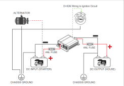
Since the house system is chassis grounded, both negative wires share a common ground. In that case, can I run a wire from the input negative terminal to the output negative terminal? And then run a single wire from the output negative (sized for the combined load of input and output) to the chassis ground?

Thank you!
 
Yes, that's what's in my manual. Both sides of the charger go to chassis ground. Does it matter that they go to the same place, separately; or can they be connected together and have a single wire to the chassis ground? Both options ground both sides to chassis ground.

It seems to me like it wouldn't matter, but then why doesn't the B2B charger just have a single negative terminal if that's the case? So I'm hesitant :)
 
The separate negatives are for electric isolated systems - think truck and a pull trailer. Non-isolated systems have a common negative (like my MotorHome).

I would contact the Renogy support line just to verify you can hook it up the way you are thinking - but I would think you can.
 
Thanks Rocketman! I'll contact them and ask.
Hey, did you hear back from Renogy? I've contacted them regarding the same issue. I was hoping that I could only connect the House (-) side since I don't have direct access to the starter (-)
 
Thanks Rocketman! I'll contact them and ask.
Mike if you have the unit can you please test for continuity between negative in and negative out?
The unit may or may not be non-isolated.
Would be good to have empirical data.
 
Last edited:
I haven't contacted them yet.

John Frum, I just tested and there is no continuity between the negative posts.
So I guess one definitely has to connect both negative ports. The question remains if it's technically ok to loop on port to the other or connect them to both to a common connection point.
In my Ford Nugget the house batteries are under the Passenger seat were I'd like to put the dcdc as well. The starter positive is also routed there to charge the AGM batteries, no access to the starter negative though
 
I would definitely use separate wires to the common point. To prevent feedback due to voltage drop and EMI from output buck-boost switcher. The voltage drop will reduce the accuracy of the charge voltage.
I hope that common point is highly conductive to both batteries. The chassis is not a good conductor.
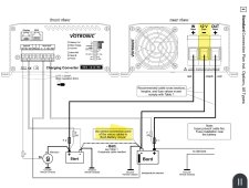
Sounds reasonable, on the other hand many dcdc chargers with common negative port work just fine. See for example the wiring diagram of the votronic 90a chargerScreenshot_20230120_193922_Xodo Docs.jpg
 
Many solar charge controllers including Victron are not isolated.
 
So I guess one definitely has to connect both negative ports. The question remains if it's technically ok to loop on port to the other or connect them to both to a common connection point.
In my Ford Nugget the house batteries are under the Passenger seat were I'd like to put the dcdc as well. The starter positive is also routed there to charge the AGM batteries, no access to the starter negative though
You can make access to battery negative terminals. Often the ground wire is bolted to chassis, add another cable to that bolt.
battery terminals for cable
battery terminals for cable with added bolt terminals
 
Sounds reasonable, on the other hand many dcdc chargers with common negative port work just fine. See for example the wiring diagram of the votronic 90a chargerView attachment 130648
Yours is isolated. Both ground wires will be carrying the return current.
The Voltronic is not isolated. It's ground wires mostly carry the output power of by the Buck/Boost Switcher, for charging and discharging the Torrids magnetic field. The bulk of the ground current returning to the source moves from Battery- to Battery-. Also it can sense voltage at the battery and compensate for wire loss.
 
Last edited:
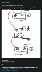
Renogy Just got back to
According to that drawing:
The neg(-) is the same in practical terms.

Both negs can go to your negative busbar that is wired to the battery negative. Both batteries should have a common ground connection in some fashion between them and to the chassis so that is the answer according to the diagram.
 
Friends don't let friends buy Renogy.
That drawing is so misleading. Resistance matters, Wire gauge matters.
 
The separate negatives are for electric isolated systems - think truck and a pull trailer. Non-isolated systems have a common negative (like my MotorHome).

I would contact the Renogy support line just to verify you can hook it up the way you are thinking - but I would think you can.
Because the grounding connection between my truck and trailer has to rely on the seven-pin connector (skinny wire) I realised it would impede the high charging current (40A). I spent the extra money on the 25' isolated ground wire. Probably would not work as well If I had gone non-isolated.
 
Yes, you can connect both -ve terminals together and then connect a single wire to chassis ground in a motorhome setup. Probably Renogy support did not understand your question.

Now the "Isolated" part has many people confused. To make it simple, imagine you have drained house battery on the RV trailer and you wanna run the microwave from your inverter. The inverter ground is connected to trailer frame and house battery +V. BOTH leads of the charger INPUT terminals are connected to the truck battery and truck is running. And as recommended by Renogy, charger is installed just next the house battery.

Now you would think if you move the inverter's +ve lead from house battery to the input terminal on the charger, you should be able to use the car alternator to run your inverter... BUT you can not with this charger since the circuit will be open due to isolated design of the charger. You have to move both -ve and +ve leads of the inverter cable to the charger input side to use your alternator power. OR just connect both the -ve terminals of the charger together like you asked (now moving the inverter +ve lead to the charger's input V+ would allow you to run the microwave using trucks power).
 
Last edited:
Back
Top