diy solar

diy solar

DIY Battery via Smart shunt to inverter integration (Solis etc)

So, is V2 ready for primetime, I honestly have not had time to look further into it. I would love to try it out on my EG4 6000xp in the next few weeks.
 
So, is V2 ready for primetime, I honestly have not had time to look further into it. I would love to try it out on my EG4 6000xp in the next few weeks.
Am running it "as production", but obviously I also change mine to test new features, so it's currently running master with some changes to the LCD display code - it did have display support in it originally but for the M5 stack devices.

The master branch and tagged release are currently in a working state and my plan is to do tagged releases with firmware files to download and then just flash using the built in ota updater than having to compile the code and upload yourself, that was why i went with using the flash storage for configuration.

If you keep the original source on your pc and then flash the new, if it doesn't work then you can always go back.

Very minor bugs at moment, like the mqtt param setting doesn't do anything and the loop times are hardcoded, i'll sort them once i've got the LCD working the way I want it.

The LCD support should lead to a system that can be pre-made and sold for people who want an off the shelf solution.

Any issues should be logged on the github page so i can go through it, sometimes lose them in a thread of comments so please do use that to log anything.
 
Last edited:
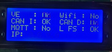
Start up screen, as everything connects it changes to OK, once all OK it changes to Run Time screen.

1000010686.jpg

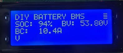
Run time screen, couple of bugs in it, the battery current part puts 2 AA's in certain scenarios and the top corner is meant to be a flashing heart beat. Random V at the bottom, not sure where that comes from!

Need to implement a enable/disable feature for lcd support as if you don't have it connected it hangs the start up for a while waiting for the lcd response.

1000010685.jpg
We're getting there tho!
 
Few random things...

1) Now I can't spot your threads easily from your smiling face, with the new avatar :(

2) Flashy new graphic, but for LiFePO4 shouldn't it be like this ;)

Capture.PNG

Random V at the bottom, not sure where that comes from!

3) I found those LCD screen do a funny wrap-around if you inadvertently write more than 20 chars on one line. So, I'm guessing here, but I suspect the "V" is the V from the end of the SOC / BV line (line 2) when the SOC goes to 100% and the final V gets pushed into character 21 position.

4) And finally, just an idea... I found it useful on my 20 x 4 LCD screen to be able to show more info (like IP address that you have on the flash screen) and, when you get round to it, temperatures etc. So I hooked up a button press that allows the LCD to be cycled around different screens.
 
Few random things...

1) Now I can't spot your threads easily from your smiling face, with the new avatar :(
But now you don't have to look at my face! it's an improvement.....
2) Flashy new graphic, but for LiFePO4 shouldn't it be like this ;)

View attachment 215942
Well, probably right but i went with what the AI generated, am happy to receive your contribution......
3) I found those LCD screen do a funny wrap-around if you inadvertently write more than 20 chars on one line. So, I'm guessing here, but I suspect the "V" is the V from the end of the SOC / BV line (line 2) when the SOC goes to 100% and the final V gets pushed into character 21 position.
Yeah it's from the second line, wraps to 4th, it's bizarre in that jumps, the SOC hasn't been at 100% and nothing would have pushed it either, but am going to change it anyway, just toying with the layout.
4) And finally, just an idea... I found it useful on my 20 x 4 LCD screen to be able to show more info (like IP address that you have on the flash screen) and, when you get round to it, temperatures etc. So I hooked up a button press that allows the LCD to be cycled around different screens.
If something goes down it changes to the start up screen to show the problem, but you don't need the IP address really, I implemented MDNS, so you just go to hostname.local and the webpage appears, can send you the code if you want, it's easy.
 
Last edited:
@SeaGal Just ordered a Raspberry Pi 5 to do my own emoncms logging, stopped doing it some years ago but decided to do it again, Home Assistant isn't really working well to be a logger with the amount of data am generating.
 
@SeaGal Just ordered a Raspberry Pi 5 to do my own emoncms logging, stopped doing it some years ago but decided to do it again, Home Assistant isn't really working well to be a logger with the amount of data am generating.
(y) love my Pi 5 which I picked up late last year. Am using it for some processing of Acrel power meter data and also for extracting RS485 COM data from my Solises (or should that be Soles?); that's based on @peufeu's Grugbus code - worth checking that out if you want to get data to and from your Solis :)

I also use emoncms for logging, though that is using the inbuilt Pi that came with the emonPi energy monitor.
 
Thanks,
Chose my correct ESPDEV platform and connection but keep keeping this error on MacOs. Might have to find a PC to try.

1716727287093.png

Error: Nothing to build. Please put your source code files to the '/Users/youcantseethis/Desktop/DiyBatteryBMS/.\src' folder
 
Thanks,
Chose my correct ESPDEV platform and connection but keep keeping this error on MacOs. Might have to find a PC to try.

View attachment 217733

Error: Nothing to build. Please put your source code files to the '/Users/youcantseethis/Desktop/DiyBatteryBMS/.\src' folder
In the platformio.ini there is a line that has .\src which tells it where to find the source. Try ./src, might be mac needs it in a different way.
 
Last edited:
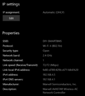
Tried on VSCode MacOS and couldn't get it to work however, it compliled and installed via windows machine. Having another issue. The WiFI comes up, connect to it but can't get to 192.168.4.1 (note my DHCP on computer when connected to ESP is 192.168.4.5). I even did a few factory resets but can't get to first setup page. Tried with two ESPs, no luck.

Tried in edge and chrome also incognito mode and not. Just can't get to config screen as you mention in readme.

1716737096370.png

1716737134573.png
 
Have you tried pinging it?

Also (I might be misunderstanding something) but isn't 192.168.4.1 the address of your DHCP server and not the ESP32?
 
If you look at the instructions you connect to the ESP WiFi (which works) then put in 192.168.4.1 to bring up the initial config page. The initial config page is not loading. Yes ping to 192.168.4.1 works. You can see that the ESP is also issuing my device an IP, the .5 address.
 
If you look at the instructions you connect to the ESP WiFi (which works) then put in 192.168.4.1 to bring up the initial config page. The initial config page is not loading. Yes ping to 192.168.4.1 works. You can see that the ESP is also issuing my device an IP, the .5 address.
what esp device are you using?

Did you do a flash erase before flashing the device?

You are correct in trying to connect to that ip address, when it's in AP mode the IP address you connect to is 192.168.4.1 or can use host name http://diy-smartbms.local/

I did test this and worked so am assuming it's something simple that we're missing.

Try opening the serial console to see what that is showing, see if there is any errors, just noticed the error is too many redirects so i'd try a phone and see if that works.
 
Last edited:
Have you tried pinging it?

Also (I might be misunderstanding something) but isn't 192.168.4.1 the address of your DHCP server and not the ESP32?
on first boot if the flash doesn't have any wifi details it defaults to creating a AP, it's default address is 192.168.4.1 and then gives out ip addresses in that subnet.
 
Back
Top