diy solar

diy solar

How to combine AC in and outs of multiple inverter/charge controllers?

boondox

Chief Engineer, RedNeckTech Industries
Joined
Mar 1, 2020
Messages
788
Hi All,

I am helping a couple of friends figure out how to put their systems together. Both of these will be inspected by the local B.D.. One is putting together 6kW of panels and the other 27kW. One will have 2*LVX6548 inverter/charge controller and the other will be a 4 stack of the same.

So my question today is: How are people combining the AC in and out? My system is older and I have Magnum inverters and use the Magnum panel box. Slick and clean, if expensive. I really like mine, it has all of the connections you need, along with AC in and out breakers, breaker for the generator input and so on. Is there a generic, brand agnostic box to use? Or how are folks combining multiple inverters? I guess it would be possible to use the Magnum or Schneider panels boxes, it just won't have the slick mount for the inverter itself.

Thanks!
 
I too am interested in this question, as should anyone who is stacking multiple Growatt, MPP Solar, Sol-Ark or other hybrid inverters in a single system. Yes, tacking a spaghetti of wires to the wall will work, but I'd sure rather have my busbars and breakers tucked away safely in a box.

Surely some company has come up with a suitable solution!

Thanks!
 
You can use a standard load center for both in and out, with a breaker for each inverter. Or if the manufacturer permits, An AC power distribution block with a single large breaker for each side.
 
You can use a standard load center for both in and out, with a breaker for each inverter. Or if the manufacturer permits, An AC power distribution block with a single large breaker for each side.
Some manufacturers have split-bus panels that you can have a "tie" breaker in the middle for bypass as well.

But, once you go with four inverters what is the most practical way to deal with the DC sides?
 
Some manufacturers have split-bus panels that you can have a "tie" breaker in the middle for bypass as well.

But, once you go with four inverters what is the most practical way to deal with the DC sides?

Everything I see seems to all be bespoke at this point. If I were to start again I would probably use copper bar on standoffs in a wiring trough with a DC breaker below each inverter above the trough and a breaker on each battery below the trough.
 
Thanks copec. Yes, I called Magnum and was told their distribution box, called a Single Panel AC/DC Distribution Enclosure, has proprietary circuits that handle the paralleling of the stacked Magnum inverters, something that is handled by plug-in parallel boards in the MPP Solar hybrid units. I talked to a Victron distributor in Reno, who said they are aware of this need and may be working on something, but then, "Call back in a year or so." Signature Solar told me they, too, are interested in this "pending further development right now tho." Which I translate as "call us in a year or so."

I like your idea of putting a copper busbar inside the trough (I'm using a 6x6" by 6' wireway from SquareD), but that's a bit of a tight fit for a high-amp busbar, at least for my newbie hands. For now it would be a 4 by 1 busbar (four inverters, one battery pair) because I've got my battery bank paralleled in a single rack, but I'm likely to add another rack at some point so I'll want at least a 4 by 2 busbar.

Yet another consideration (and more copper in the wireway/trough) is a bus for connecting a generator to all four AC inputs on the inverters, which I'm told is the only way to charge the battery bank when the sun ain't shining. (I'm fully off-grid.)

With all the stacked hybrid inverter systems flooding into the market, this strikes me as a great opportunity for Midnite or Victron or other innovator...
 
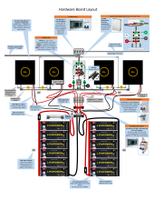
So I have been trying to figure out this issue as well, and after several amounts of feedback, plus working with the techs at Signature Solar, this is what I'm building for a totally off-grid home. See image showing how I will layout my board below.
I have a 14.1 kw solar array broken in to 4 groups, each feeding one EG4 6500ex MPPT Charge Controller. From there the rest is pretty straight forward. I'm using a lot of bus bars to combine the DC, and the AC wire sections. My AC wires from the charge controllers are fed to what will be a custom AC Combiner Box using busbars put in a stair step setup to make combining the wires easier, then run in conduit to the main house panel, and the neutral and ground wires will be put together there (bonded). The DC wires from the charge controller go to busbars that feed two large batter racks I'm combining with 1,000Amp busbars to make them one giant 61kw battery bank. I've also added appropriate wires sizes, breakers and fuses. Once I have this built and reviews by the State of Colorado inspector I will let you know the results. I hope this will help others.
  • I did look into using a wireway or trough, but they are way too over priced, and PVC conduit was much more affordable.
  • I used Southwire's conduit fill calculator in determining the size pipes I will be using for the conduits per NEC code.
  • Cable sizes were based on recommended wire sizes by the EG4 manufacturer.
  • The only thing not shown in this diagram is the PV shutoffs next to the ground mounted solar arrays.

Home.Power.Station.png
 
Last edited:
How are people combining the AC in and out?
To be clear, you are not talking about combining in and out, you are talking about connecting inverter AC in to a source and AC out to a load. I only have one device and I use a breaker on each end despite the fact that my Inverter also has a breaker.
I have a breaker on my main service panel that feeds my inverter. If one has several inverters then use several breakers. I believe that is what the building department will want, but your code may be more flexible.. Similar I use breakers on the sub panel but that is not as important if you are going direct to the sub panel lugs. For multiple inverters it is probably better to use separate breakers but I do not know the specific code for that situation. Some codes require a visable means of disconnect so you can work on the sub panel safely.
 
Last edited:
To be clear, you are not talking about combining in and out, you are talking about connecting inverter AC in to a source and AC out to a load. I only have one device and I use a breaker on each end despite that my Inverter also has a breaker.
I have a breaker on my main service panel that feeds my inverter. If one has several inverters then use several breakers. I believe that is what the building department will want, but your code may be more flexible.. Similar I use breakers on the sub panel but that is not as important if you are going direct to the sub panel lugs. For multiple inverters it is probably better to use separate breakers but I do not know the specific code for that situation. Some codes require a visable means of disconnect so you can work on the sub panel safely.
What you wrote was how I interpreted his request...
 
I'm using a lot of bus bars to combine the DC, and the AC wire sections. My AC wires from the charge controllers are fed to what will be a custom AC Combiner Box using busbars put in a stair step setup to make combining the wires easier...
I did look into using a wireway or trough, but they are way too over priced, and PVC conduit was much more affordable.
You might want to re-think that. Polaris connectors (insulated multi-port taps) are really the way to do the AC connections. Anything short of that is really an accident waiting to happen.
 
You might want to re-think that. Polaris connectors (insulated multi-port taps) are really the way to do the AC connections. Anything short of that is really an accident waiting to happen.
Thank you for the feedback! I checked out this guys video on those:

And I like them better than using busbars to combine my AC wires, good call, I'm ordering these and will update my graphic. I think I'll still need to use the Blue Sea 1,000Amp busbars on the DC side though for the batter bank combining.
 
Last edited:
I used Southwire's conduit fill calculator in determining the size pipes I will be using for the conduits per NEC code.
For those following your diagram, it’s better to clarify that number of current carrying conductors derate in the conduit may need to be applied. If above 24” conduit between boxes.

What software did you use to draw this? Very Neat!

IMO wire way or separate cables is the easiest to do this without understanding code details.

And I like them better than using busbars to combine my AC wires, good call
What do you mean by bus bars? Do you mean a combiner subpanel with regular North American breakers?

IMO feeder calculations are less well understood than busbar. You can read about both in 705.12 (load side connections). There are more articles and videos you can Google on busbar calculations than feeder calculations. Feeders with Polaris style taps can be more compact but you will need to add junction boxes (replacing the conduit fittings) or wire way to hold them. Conduit bodies almost never have the box volume to accommodate the box fill.

If you use feeders instead of multiple parallel conductors you no longer need to derate for number of current carrying conductors. However the Polaris taps and more splice boxes will probably cancel out the size and wire savings
 
You might want to re-think that. Polaris connectors (insulated multi-port taps) are really the way to do the AC connections. Anything short of that is really an accident waiting to happen.
I don’t follow. For smaller circuits isn’t it cheaper and easier to calculate if the inverters are combined together in a subpanel? This is far more common of an install in the US. EG, comparing the cost of extra #8 or #10 and breakers vs Polaris taps. You need 3 Polaris taps to save some wire and breakers. 1 Polaris tap is already the cost of a breaker. 705.12 math for bus bars is better explained in the code and online than the math for feeders IMO.

In fact Enphase, Tesla, etc source panelboards from other manufacturers to put in their gateways and combiners so you can do it this way.

I will agree if you are combining bigger ampacity / AWG circuits taps start to have advantages
You thinking my 250amp busbar approach for combining these AC wires is probably acceptable? This is for US based off-grid property.
 
For those following your diagram, it’s better to clarify that number of current carrying conductors derate in the conduit may need to be applied. If above 24” conduit between boxes.

What software did you use to draw this? Very Neat!

IMO wire way or separate cables is the easiest to do this without understanding code details.


What do you mean by bus bars? Do you mean a combiner subpanel with regular North American breakers?

IMO feeder calculations are less well understood than busbar. You can read about both in 705.12 (load side connections). There are more articles and videos you can Google on busbar calculations than feeder calculations. Feeders with Polaris style taps can be more compact but you will need to add junction boxes (replacing the conduit fittings) or wire way to hold them. Conduit bodies almost never have the box volume to accommodate the box fill.

If you use feeders instead of multiple parallel conductors you no longer need to derate for number of current carrying conductors. However the Polaris taps and more splice boxes will probably cancel out the size and wire savings
Used Microsoft Publisher. Regarding the bus bars question, you'll note in my drawing above, I'm using bus bars to combine the wires from 4 separate EG4 6500ex Inverters together in a box using a separate bus bar for each of the sets of wires, N, G, L1 & L2 so I only have 4 wires traveling from this AC Combiner box as I'm calling it to the main house breaker panel, which will be located in the garage about 15 linear wire feet away.
 
You thinking my 250amp busbar approach for combining these AC wires is probably acceptable? This is for US based off-grid property.
No I misunderstood what you meant by busbar since busbar is usually meant a different way in AC side than DC side.

Yes I get that you have 4 wires traveling to a panel, but you have L1/L2/N (should count as two CCC) coming from each inverter, and you accumulate more and more in the conduit. Above 3 current carrying conductors you have to apply derating table unless it's an exempt situation.

Off-grid doesn't de jure exclude you from NEC. It only mostly excludes you from POCO oversight, but your state laws may still regulate you as a producer.

Shouldn't this be vetted in your plan check, before it's built and your inspector shows up? Not that you should expect plan check to catch all issues.

OK, so you are NOT using a subpanel/panelboard busbar. You are using busbar in the battery pack/DC system sense. Do you have explicit evidence (code citation, UL listing / manufacturer instructions) saying that this is an accepted method? I haven't seen this implementation.

The Polaris connectors and subpanel are standard approaches and they are certainly code compliant. And they should be easier. If you only need 125A (good for 100A inverters output) then you can use a fairly compact 125A busbar subpanel with 125A main, following Sum of Breakers rule in 705.12. You can stack 4 * 24A (4 30A breakers) onto that. It probably becomes unwise to use a combiner panel above 125A from size and expense perspective.

If you use Polaris Taps OR busbars you will have to use the feeder calculations in 705.12. If you have a lot of power involved then Polaris will be preferred. The easiest way to pass those if you don't understand the text/math is to use grossly oversized wires. But of course you should try to understand what they want you to do.
 
Ah actually. Since you're putting this in a larger enclosure, and it's not subject to weather etc. Polaris connectors are better for awkward places exposed to weather / have a tight fit

There are cheaper terminals than Polaris that you can use. They're basically the AC version of DC bus bars.

I don't know what they're called unfortunately, you might ask on a DIY electrical forum since there would be a higher density of electricians etc on those than here.

EDIT: Power Distribution Blocks. This isn't the right one for what you want but this is the form factor and termination type (screw clamp terminals)

 
You are also availing of Feeder Tap rule by aggregating multiple smaller conductors into #2, so read up on that. It imposes conduit length rules on your installation. Along with ratio between your larger and smaller conductors. This rule governs when you have a larger OCPD than the smallest conductor on a circuit.

You may not be allowed to use this with the EG4 because feeder tap rule requires there to be a OCPD on the smaller conductor. I don't know if the EG4 has a breaker in it to achieve this.

If you use a subpanel you do not need to avail of this rule.
 
Back
Top