diy solar

diy solar

How to combine AC in and outs of multiple inverter/charge controllers?

Technically, that is 4 current carrying conductors, and requires derating ampacity to 80%

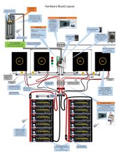
Are these two inverters in parallel, or stacked for 120/240V split-phase?
If split phase I would think one G, two L (L1 and L2), one N.
4 inverters in all, two on each side, each set is in parallel producing one leg 120v.
 
I suppose I could run each set of wires from each inverter in separate 1" conduits instead of combining them together before I feed them to the sub-panel. I think that would alleviate the need for derating ampacity.
 
I suppose I could run each set of wires from each inverter in separate 1" conduits instead of combining them together before I feed them to the sub-panel. I think that would alleviate the need for derating ampacity.
That is uglier though and it’s probably cheaper to go up in wire size. A lot of extra work to avoid multiplying by one factor
 
For my 4x 120V inverters, I used 2x 2-pole breakers.

Each stacked pair of 120V inverters produced 120/240V split-phase.
At the breaker panel they had one each L1, L2, N, G. Routed in conduit, and at a Tee I used split-bolt splice (wrapped in rubber and vinyl tape) to branch off two N and two G for the two inverters. I had to keep track of which pair, to ensure N carries L1 - L2 current, not L1 + L1 current.
That configuration was done twice for two sets of stacked pairs.

Since your two G, two N, two L has only two "line", I suppose those each split to two inverters paralleled on one phase?
You might do the same for N and G.

I suppose I could run each set of wires from each inverter in separate 1" conduits instead of combining them together before I feed them to the sub-panel. I think that would alleviate the need for derating ampacity.

Yes, that would too.
I think with sufficiently oversize conduit there would be no technical issue (air circulates and heat spread), but letter of the NEC.
If routed in a huge 6x6 box, seems derating is supposed to apply too.

I used 6 awg, could have used 4 awg.

That is uglier though and it’s probably cheaper to go up in wire size. A lot of extra work to avoid multiplying by one factor

But as described it seems like 4 current-carrying conductors for 4 inverters (branched apart later?) and I think can be reduced to 3 current carrying conductors, for no derating.

If excess number in a 2' or shorter length, derating not required. Possibly branch out from first inverter? Daisy-chain?
If you do have just 2 "L", they must be heavy enough for current of two inverters.
 
A sketch of inverter and electrical panel physical placement with distances would be useful.
 
But as described it seems like 4 current-carrying conductors for 4 inverters (branched apart later?) and I think can be reduced to 3 current carrying conductors, for no derating.

You can argue that it is only 3 or even 2 CCC since (1) they can share neutral (2) they are L-L-N on opposite legs. But this is more complex than the usual case of doing this for utility power where the correct voltage current relationship is enforced by a transformer instead of properly configured stacked inverters. The split transformer physically cannot do something wrong. While inverter can do something wrong if misconfigured in software. I guess if the legs deviate from being opposite voltage then all your 240 loads will break. If there are only 120v or MWBC loads then there could be a silent but dangerous situation with overloaded neutrals. That danger is in the whole system not just this one conduit we’re backseat quarterbacking.

If 2 feet between boxes then you are exempt from CCC. Conduit bodies don’t count for this lifehack.

I believe you can put as many conductors as you want in a box or wire way.
 
You can argue that it is only 3 or even 2 CCC since (1) they can share neutral (2) they are L-L-N on opposite legs.

I will argue it is 4, because the two N only join at breaker panel.
that is why I suggest joining them (somehow) at the inverter. Then N carries L1 - L2

But this is more complex than the usual case of doing this for utility power where the correct voltage current relationship is enforced by a transformer instead of properly configured stacked inverters. The split transformer physically cannot do something wrong. While inverter can do something wrong if misconfigured in software. I guess if the legs deviate from being opposite voltage then all your 240 loads will break.

Yes, if two inverters free-run you could overload neutral. Double neutral wire protects against that.

240V loads would see 0V if inverters misconfigured parallel rather than 180 degrees apart for split-phase.
If free-running e.g. no synchronizing cable, 240V loads will see everything from zero to 240Vrms.

If a balancing transformer is connected, that will fight (look like a short) when phase isn't 180 degrees. Or voltage differs.
 
I will argue it is 4, because the two N only join at breaker panel.
that is why I suggest joining them (somehow) at the inverter. Then N carries L1 - L2

Yes, I meant you can get it down to fewer CCC if you configure appropriately. I cannot say what is the right best practice for potential future proofing, etc.

240V loads would see 0V if inverters misconfigured parallel rather than 180 degrees apart for split-phase.
If free-running e.g. no synchronizing cable, 240V loads will see everything from zero to 240Vrms.

Having 240V loads should help you detect this, since it's an obvious misconfiguration.

120V only is definitely in the silent but deadly camp. I would guess 20% of MWBC in the country are messed up but nobody ever notices, and you only call in electrician if something doesn't work. I mean I messed mine up for a few months.

I think the balancing transformer fighting a messed up config would probably throw an error on the inverter. Hopefully.
 
A sketch of inverter and electrical panel physical placement with distances would be useful.
Everything is very close together. The EG4 inverters are 8 in apart. The main house panel is also in the garage about 15 linear ft from the sub-panel. Hope that helps.
 
I think it's safest to plan this assuming that you will have to do the 80% derate. You have to be good at both visualizing how to run the conduit, and understanding how 24" rule is applied/measured, to apply it.

90C allowed temperature (satisfied if you use THHN conductors, in solid PVC or metallic conduit)
91% ambient temperature derate (took the 31-35C/87-95F row from the NEC table)
80% CCC derate - 4 current carrying conductors (Line and Neutral for each of the inverters on a side)

70A required ampacity (I didn't scroll up all the way to see the actual 125% ampacity)

Copper #4 is 95A @ 90C, 85A @ 75C
95 * 0.91 * 0.8 = 69.16A

If you need 82% ambient temperature derate because the temp where the inverters are is above 95F
95 * .82 * .8 = 62.32A. Have to go back in the thread to see if this is enough for your inverter output.

So you can see that 80% CCC derate + a high ambient temperature derate gets pricy

You might look for 4-4-4-6 or 4-4-4-8 copper SER / NM / MC, that can be installed without conduit and avoids the 80% derate. #6 SER, MC are good to 65A @ 75C, but not NM, it is only allowed to 55A @ 60C

(note: I'm not sure if EG4 terminals support copper so let's assume they don't, also for shorter runs copper and aluminum don't have a big absolute cost difference. For the house to combiner panel run, the terminals definitely support aluminum and they are big wires, so copper and aluminum can be cross shopped based on local availability and cost)

Tables are here

Looked it up -- 6500W / 120V * 125% = 67.71A on each leg
 
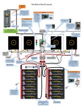
Ok, based on our conversations, I've made some additional changes. I went ahead and separated the AC wires from each inverter into their own 1" conduits to feed to the sub-panel. So now the conductive wire issue is no more. Each conduit only contains two conductive wires + a ground.
The 200A sub-panel will have a 150A main breaker, and the back feeding breakers are 2 double pole 70A. The combined wire from here will be 2/0 and run about 15 linear ft to the main 200A house panel that contains a 200A main breaker. This panel is where I will bond the G and N together. Personally, I kinda like the PVC piping approach, easy for me to work with, and.. well... I think it looks kinda cool. ;- )
Did you guys have any other thoughts on this, any reason an inspector with Colorado would not approve of this setup?

The only thing we haven't discussed is I have eight 10 gauge wires running from all the solar arrays in a 1" conduit into the garage to a PV disconnect box noted below (4+,4-), 20A breaker for each array set. There are 31 panels, each panel is 50v, 11.89A and 455 watts. I've put them in groups of 8 = 400v, with the 4th one 350v, well under the 500v maximum allowed by the EG4 inverters.
McGuffin.Home.Power.Station--vs2.jpg
 
Did you guys have any other thoughts on this, any reason an inspector with Colorado would not approve of this setup?
  • Whether the 200A breaker in your main is acceptable. It should be fine, it's not the protection for that wire, since the power comes from the subpanel.
  • Whether you run into issues with your system starting at the subpanel, but the N-G bonding happening at the main. Arguably the first means of disconnect is at the subpanel, so the N-G bond needs to happen there. If this was utility power then that's how it would need to be done -- what you have with the N-G bond at that main panel. I'm not sure about off-grid only power. You would be allowed to do it the way if drawn if you transferred to off-grid power during a power outage.
Hmm. I'm wondering about the N-G bond issue as well. The NEC stipulates that is should occur at the location where the power comes in and the first breaker is, which in a typical home would be the Main panel. But my power first comes in at the sub-panel before feeding to the Main panel, so it would seem the N-G should happen in that panel only, and I should also remove any N-G screws in the 4 inverters if they come with one already installed.
 
This is outside my knowledge. Also extending the ground (I think it’s called GEC) has special rules to the bonding point at the service. Which I don’t know since I’m just a Internet electrician and I doubt I will ever do GEC by myself instead of hiring it out.

After the bonding point (now called EGC) it’s much more relaxed.

As such it is fraught to try to repurpose EGC as a GEC.
 
Here is the updated setup with the N-G moved to the sub-panel where the power comes in and the first breaker is located.

McGuffin.Home.Power.Station--vs2.jpg
 
"200A sub-panel will have a 150A main breaker, and the back feeding breakers are 2 double pole 70A"

When you say "backfeed" it makes me think of PV breakers in a panel fed by grid with 200A. 200A x 120% = 240A, 240A - 150A = 90A so only a single 70A PV breaker would have been allowed.

But for your off-grid system, the only source feeding the panel is the two 70A breakers? Or do you have AC coupled PV as well as battery inverter? I think 4x EG4 is the only AC source I see in the drawing. So I don't think 120% rule applies.

What is the 150A breaker for? Just switching off power through 2/0 cables to main panel, which has 200A breaker?
I don't think you'll ever hit 150A, much less 200A. I think 200A breaker could be used in either/both panels. Same goes for 150A breaker.

By the way, there are some 225A busbar panels. Maybe only in QO series, not homeline.

Neutral ground bond seems like it's in the right place now. From there, wires to ground rod(s), gas and water pipes, foundation steel if available.
 
Back
Top