So your breakers aren't really main breakers, and main breaker is hard to define for your situation. I think main refers to the breaker from the utility / main power source. I guess both of your 70A are main breakers. They are always-on power sources (unlike grid tie inverters which are interactive), which is why you must have hold down. And I think you must label the a certain way. You can google for pictures of the standard required solar / renewable generation labels, there's probably a variant that applies to your specific situation.
OK, so I mentioned this because:
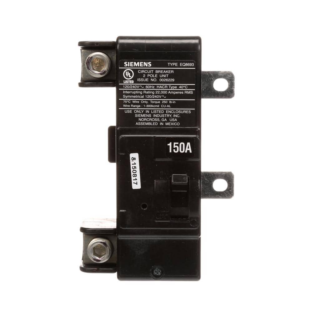
- you may be able to find a better deal on panel with 200A MBK packaged in, than 150A MBK + panel combo, or Main lug only combo + separate MBK kit (that's what you have in your cart right now)
- If you can find a better deal, maybe going up to bigger wire that can hold 200A, and pairing that with the 200A breaker, is cheaper and arguably more future proof if you want to add more inverters in the future. Switching to aluminum instead of copper feeder could help with this too, since the cost of copper feeder starts getting even more ridiculous as you get to large AWG
- I think your house panel can be main lug only OR main breaker. In this case it's local shutdown, as you have indicated in your picture. Now, since it's on the load side, you can use any breaker size, 200A too, it's just a switch. But putting 200A on a 150A wire is potentially confusing for future people (or if you yourself forget later). You can address the confusion by I guess labeling the house panel more clearly that it's 200A breaker but 150A feeder.
- Another theoretical advantage of making the house panel breaker match the feeder is that you can tie in solar over there in the future. EG maybe that's a good place to land some microinverters or string inverters. And those can be AC coupled to your inverters in the other location. It's a lot easier to get a code compliant and safe situation if the main breaker there matches your feeder, instead of MBK being bigger.
- Similarly, if you decide to use lugs instead of breaker over there, if you size the feeder to 200A just like the busbar, it's harder to make a calculation mistake. VS if you have feeder of 150A as you have right now, then whoever does future calculations for adding power sources on the main house panel will need to ignore the sticker on the panel and use 150A as the busbar. I would guess >50% of people will get this wrong.
Sorry, this may be getting too far in the weeds. Though as I've said before, I've been asked by solar installers to simplify my breaker set up along similar lines. In my case I had a 100A feeder with 100A breaker on MSP side and 200A built-in breaker on the distribution subpanel side. They weren't happy with either lugs or 200A, they wanted me to put a 100A backfeed breaker to match the feeder. This actually ended up helping me out, because right now I'm expanding my solar, and it's more convenient for me to put some of the new inverters on my distribution subpanel than other places in my system.
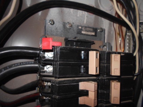
That looks reasonable. I think there's a second type of retainer clip from Siemens, they have two or three different panelboards. Most of the branch circuit breakers are the same but the retainer is different and the mains are different. You want to make sure you don't buy the wrong one. The Siemens catalog I think is decent in telling you all the different shapes and sizes and busbars, as well as which hold down / main breaker / other accessories are the right ones to buy.