diy solar

diy solar

hwy17's Orion battery build

Is there any room at the top to add some sort of padding for additional protection?
Yeah good idea. I could put some HDPE up there if I figure out how to bolt or adhere it.
If there is any earthquake that severe you'll more than likely have bigger problems to deal with...
Like the propane water heater adjacent to my battery bank... If I end up on the news there will be one hell of a thread about it!
 
Yes, exactly :) ... when referring to digital electronics a NOT gate is also called an inverter. The 7404 chip contains 6 of them, hence referred to as a hex inverter by the chip manufacturers.

The point (=joke) I was making in post #2 and #4 (https://diysolarforum.com/threads/hwy17s-battery-build.72380/post-917485) was that @hwy17 used a NOT gate / digital inverter symbol rather than a
1699473414237-png.176758
symbol
Gotcha. I’m slow. ?
 
I would run additional support, maybe strut, on the backside that joins the 2 boxes. Fasten the bottom to the concrete and the additional support to the wall.
Unistrut mounted to the studs and then boxes mounted to the struts is a nice idea. But another research project for me to figure out strut bolts.
 
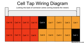
I'm planning to use a pack split fuse, with a class T between cells 8 and 9. The Orion JR2 uses split cell management interfaces so this will not affect voltage readings and the passive balancers.

It's at the edge of my electrical understanding though whether a resistor in the middle of a bank affects the balance of charging. On one hand the resistor affects current equally across the whole circuit, but afaik voltage does drop in a gradient along the circuit.

So does that mean in any series of cells the last cells on one end are always getting a different voltage, resulting in an inherent imbalance force, which will be worsened by an added resistor in the middle of the string? I really don't know.
 
I'm planning to use a pack split fuse, with a class T between cells 8 and 9.
Why?
It's at the edge of my electrical understanding though whether a resistor in the middle of a bank affects the balance of charging. On one hand the resistor affects current equally across the whole circuit, but afaik voltage does drop in a gradient along the circuit.
IMHO it wouldn't affect charging as the current through all cells would be the same. At the end of the day, every bus-bar connection is a small value resistor.

However, if there was a measurable voltage drop over that resistance, that would affect the cell balancing. The BMS will be measuring the cell voltages and an extra resistor that is only in series with one cell (either cell 8 or 9 depending on which side of the resistor you connect the balance lead) would result in that cell reading a bit higher than the actual cell's voltage is.

Obviously any voltage drop will be linear to current flow and may be immeasurable anyway.
 
Mostly I find it a neat and convenient mounting location, and saves me having to buy a holder and mount the holder inside the case and the extra cable the holder adds. On top of that, I like that it protects some direct short circuits of the terminals.
IMHO it wouldn't affect charging as the current through all cells would be the same. At the end of the day, every bus-bar connection is a small value resistor.
Good, that is my hope.
However, if there was a measurable voltage drop over that resistance, that would affect the cell balancing. The BMS will be measuring the cell voltages and an extra resistor that is only in series with one cell (either cell 8 or 9 depending on which side of the resistor you connect the balance lead) would result in that cell reading a bit higher than the actual cell's voltage is.
I believe I won't be affected by this as the Orion JR2 uses separate cell interfaces for 1-8 and 9-16, with a negative tap on the terminal after the fuse on cell 9 to start the second interface's reading. Orion approves fusing at this specific midpoint.
Capture.PNG
 
I have 3 thermistor taps on the BMS and they come in a free hanging probe or terminal mount.

I'm thinking maybe 2 terminal mounts at either end of the pack and one free hanging taped to the back side that's closest to the cold/hot exterior wall.
 
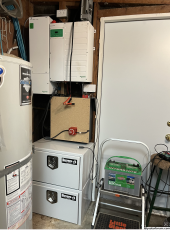
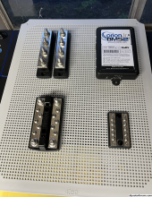
The toolbox arrived, the first one got delayed so I ordered another and then they both showed up. I don't like needlessly returning heavy items, so I think I'll just build it now as more expansion room. Also got one of the chinese clear case electrical boxes off amazon to house the BMS, bus bars, relays, and contactors. Kind of a mental tug of war where to put the main bus, but I think it's gravitating up and to the left near to the inverter. This controls box will get mounted to the top(front) of the server rack battery for now.
Screenshot 2023-11-19 at 6.02.42 AM.png
Screenshot 2023-11-19 at 6.02.22 AM.png
 
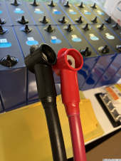
All looks good - hope those crocodile clips aren't powered up though ⚡
 
1700517562411.jpeg
2300w power supply with configurable charge profiles. But I didn't buy the $50 configuration tool yet since I think it might work for me in PS mode.
 
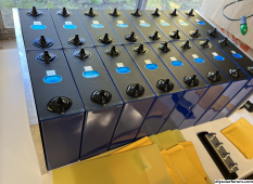
Assume there will be insulation between the cells - guess that's what the yellow covered sheets are?

Ignore that, you've already mentioned that in post #30. Need more :coffee::coffee:
 
Yeah my compression plan is going to have serious short circuit hazards so there will be 1/16th" FR4 all around the bank and thinner in between the cells on every surface. I'm still not sure about FR4 I think there should be a more cost effective safe solution. But I can think about that for the next one.
 
Honestly not sure if they are ideal but here is what I use, definitely cost effective.
Boards on the bottom and on the ends, sheets in between.
The sheets cut easily enough with some heavy duty scissors / shears.
The boards rip down like butter on the table saw, looks like fresh snow when you are done...
I've had no issues with 3 packs. I plan to keep this route going forward but I will likely be housing the packs in a steel enclosure for the next build.
Arrow Home Products 10pc Flex Cutting Mat, White https://a.co/d/4SEmr0L
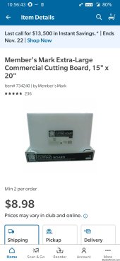
Screenshot_20231121-105445.jpgScreenshot_20231121-105644.jpg
 
I had only considered HDPE 1/2" cutting boards before FR4 when I was looking at compression options, and FR4 wasn't gonna be a lot more than that.

But now that I see stuff like this, yeah that would be $100 saved:


Especially cause I'm now considering a $60 bench shear just to cut the 1/6th" FR4... but it will help with my DIY bus bars too.
 
Back
Top