diy solar

diy solar

I had a DC breaker burn up. Why?

Mr-Sandman

Solar Enthusiast
Joined
Dec 28, 2021
Messages
351
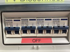
So after about 1 year of service this CHTAIXI DZ47Z-63 series 32 amp breaker failed. I would like to understand why.

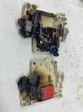
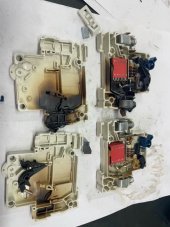
The breaker that failed is a 500v 32 amp DC breaker. This breaker is used as an indoor disconnect for a PV array into the Solar Charge Controller. The Solar panels feed into the TOP of the breaker using 8 gauge wire and the SCC is hooked to the bottom of breaker. There are (4) 455w solar panels in (2) strings making for about 90v and 20 amps max. There are no shorts and the breaker was found NOT tripped as shown in picture, with no connectivity going thru it anymore. Only the positive side failed, no signs of anything wrong with negative side. The 8 gauge cable on the burnt end was still secure and tight "no Ferrules used, but solid connection". The breaker and cable next to the breaker got extremally hot, no other connection in the circuit show signs of heat.

Thoughts on what went wrong here? Did I hook something up wrong? Maybe a bad breaker?
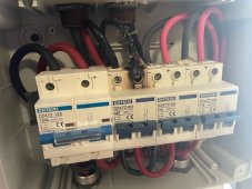

image5.jpeg
image6.jpeg
image2.jpeg
image1.jpeg
 
Last edited:
That is very interesting. I honestly have no clue as to what happened. But I would be interested if you can test the other breakers to see if they actually work as they are supposed to. I have seen videos of these breakers burning when hooked up backwards like the plus to the minus and the minus to the plus. I have quite a few of these style breakers I will see if I can do some experimenting to get one to burn up. I have about 20 deployed though and have never had any problems. In the end it could just be a bad breaker IDK.
 
So after about 1 year of service this CHTAIXI DZ47Z-63 series 32 amp breaker failed. I would like to understand why.

The breaker that failed is a 500v 32 amp DC breaker. This breaker is used as an indoor disconnect for a PV array into the Solar Charge Controller. The Solar panels feed into the TOP of the breaker using 8 gauge wire and the SCC is hooked to the bottom of breaker. There are (4) 455w solar panels in (2) pairs making for about 90v and 20 amps max. There are no shorts and the breaker was found NOT tripped as shown in picture, with no connectivity going thru it anymore. Only the positive side failed, no signs of anything wrong with negative side. The 8 gauge cable on the burnt end was still secure and tight "no Ferrules used, but solid connection". The breaker and cable next to the breaker got extremally hot, no other connection in the circuit show signs of heat.

Thoughts on what went wrong here? Did I hook something up wrong? Maybe a bad breaker?
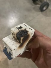

View attachment 152477
View attachment 152478
View attachment 152479
View attachment 152485
In the picture with it in your hand, it clearly shows the cable intact, but Slagle on the surface of the breaker.
My bet is simply a faulty breaker,and inadequate arc suppression.
Cable connection looks just fine.
 
How many amps nominal are intended to flow through it? 8 AWG usually means quite a few parallel strings.
 
That is very interesting. I honestly have no clue as to what happened. But I would be interested if you can test the other breakers to see if they actually work as they are supposed to. I have seen videos of these breakers burning when hooked up backwards like the plus to the minus and the minus to the plus. I have quite a few of these style breakers I will see if I can do some experimenting to get one to burn up. I have about 20 deployed though and have never had any problems. In the end it could just be a bad breaker IDK.

When did you get back!?
 
I suppose failed to extinguish arc is a possibility (if used over-voltage or wrong polarity.)
Solar panels on top appears to be correct polarity, assuming red is positive.

But my first guess would be poor connection. Wires settle and become lose. My approach now is to rotate wire back and forth and re-tighten, repeat until screw stops tightening.

The specified torque is quite low, and doesn't crush the air out of the strands. Just pressure on a bunch of cylinders that yield slightly. Compare that to a crimper making gas-tight seal.

How about the other connections? After high current has been flowing or a while, check temperature. Use DMM to check voltage drop from screw to wire.
 
FWIW, I take new systems up to their full rating or more if I have enough space heaters (etc) with me then measure voltage drop across the entire system and then each individual connection. This will reveal problem components, crimps and connections almost immediately.

Thermal cameras are nice but they are expensive and require a bit of know how to really use properly. I have one and I still use the voltage drop test most often.
 
I would be very interested if the remaining terminals have any “give” if you snug up on them. I have the same brand breaker but 1000V 16A. The terminals are terrible. The only way for it to hold 8 thnn (edit; actually 10 gauge) is to strip it double normal and fold it in half, then insert. If I don’t do that, it’ll fail my wiggle tug test. Even so in time they can be tightened some more.
IMG_0718.jpeg
 
Last edited:
How many amps nominal are intended to flow through it? 8 AWG usually means quite a few parallel strings.
This only had 2 string of 2 panels on it. So about 90v at 20 amps max. I thought a 32 amp breaker would be adequate for the 20amp max load.
 
Guys I agree at first look, you would think a poor wire connection. I CUT the wire to remove the breaker and the wire is still secured in the breaker connection. I cannot pull any strands out, its a solid connection still.

I don't think it was a failure to extinguish on trip, as the breaker was not tripped when I found it in this condition.

I'm wondering if there was a poor connection where the breaker makes the connection internally that heated up until it started arching?
 
I would be very interested if the remaining terminals have any “give” if you snug up on them. I have the same brand breaker but 1000V 16A. The terminals are terrible. The only way for it to hold 8 thnn is to strip it double normal and fold it in half, then insert. If I don’t do that, it’ll fail my wiggle tug test. Even so in time they can be tightened some more.
Is that 8 awg in 63A breaker? Or 16A breaker? Some of these components have an extraneous "63" in the part number.
Does it say what gauges should fit?

Maybe they expected fine stranded wires and ferrules. The Europeans seem to like those.

This only had 2 string of 2 panels on it. So about 90v at 20 amps max. I thought a 32 amp breaker would be adequate for the 20amp max load.

32 ... 16 that must be amps.
Probably explains the "63A" DIN rail transfers switch I got that buzzed. Don't know what amperage it really was.
The 6 awg coarse strand I used did fit securely.
 
Guys I agree at first look, you would think a poor wire connection. I CUT the wire to remove the breaker and the wire is still secured in the breaker connection. I cannot pull any strands out, its a solid connection still.

I don't think it was a failure to extinguish on trip, as the breaker was not tripped when I found it in this condition.

I'm wondering if there was a poor connection where the breaker makes the connection internally that heated up until it started arching?
It could be. I do know from experience that these breakers and fine strand wire are difficult to keep tight.
 
Is that 8 awg in 63A breaker? Or 16A breaker? Some of these components have an extraneous "63" in the part number.
Does it say what gauges should fit?

Maybe they expected fine stranded wires and ferrules. The Europeans seem to like those.


32 ... 16 that must be amps.
Probably explains the "63A" DIN rail transfers switch I got that buzzed. Don't know what amperage it really was.
The 6 awg coarse strand I used did fit securely.
The DZ47Z-63 is the series of breaker, the C32 or C16, etc. is the rated amperage. The one that failed is a C32 "32 amp" with about a 20amp max load on it during peak output.

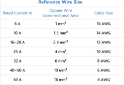
Here is the wire size chart the manufacture supplies for these breakers.


1686450623819.png
 
It appears that there was a failure on the positive side of the DC breaker used as an indoor disconnect for your PV array. Here are some reasons for the failure:

  1. Overload: Although you mentioned that there were no shorts, it's possible that the current flowing through the breaker exceeded its rated capacity of 32 amps. Even though the solar panels have a combined maximum current of 20 amps, there may have been intermittent spikes or a temporary increase in current that caused the breaker to overheat and fail.
  2. Loose Connection: While you mentioned that the cable on the burnt end was secure and tight, it's still possible that there was a loose connection or a poor contact point within the breaker. This can lead to resistance and heat buildup, eventually resulting in failure.
  3. Defective Breaker: It's also possible that the breaker itself was faulty or had a manufacturing defect. Even high-quality components can occasionally fail prematurely. If the breaker was defective, it could have caused excessive heat and subsequent failure.

Either way, this is now a "non trustworthy system" until you find the culprit and I wouldn't rule out either of those above. You are considered very lucky that you can even talk about this. Consider early warning smoke detectors with heat rise detection via sms text with sirens.
I have a whole shit ton of electrical draw with clean agent systems for my servers. When they load shed cold boot I still pray.

Try to get some good sleep because tomorrow will be a big day of troubleshooting for you. It's most likely a bad breaker(s) hopefully.


Mike
 
Last edited:
It appears that there was a failure on the positive side of the DC breaker used as an indoor disconnect for your PV array. Here are some reasons for the failure:

  1. Overload: Although you mentioned that there were no shorts, it's possible that the current flowing through the breaker exceeded its rated capacity of 32 amps. Even though the solar panels have a combined maximum current of 20 amps, there may have been intermittent spikes or a temporary increase in current that caused the breaker to overheat and fail.
  2. Loose Connection: While you mentioned that the cable on the burnt end was secure and tight, it's still possible that there was a loose connection or a poor contact point within the breaker. This can lead to resistance and heat buildup, eventually resulting in failure.
  3. Defective Breaker: It's also possible that the breaker itself was faulty or had a manufacturing defect. Even high-quality components can occasionally fail prematurely. If the breaker was defective, it could have caused excessive heat and subsequent failure.

Either way, this is now a "nontrustworthy system" until you find the culprit and I wouldn't rule out either of those above. You are considered very lucky that you can even talk about this. Consider early warning smoke detectors with heat rise detection via sms text with sirens.
I have a whole shit ton of electrical draw with clean agent systems for my servers. When they load shed cold boot I still pray.

Try to get some good sleep because tomorrow will be a big day of troubleshooting for you.

Mike
Ya I'm not willing to just slap another breaker in there and call it good. I do consider myself lucky, as this system is inside my home.

I do have a smoke detector mounted directly above this system that sends push notification directly to me. It did NOT alert. I never smelt smoke and honestly I'm not even sure when this happened, I just noticed reduced output and found this string of panels not working.

The breakers are sealed pretty well in the plastic enclosure you see in the first pic. I think the breaker box would have contained any smoke pretty well. I do not smell any burnt smell in the room either.
 
Last edited:
I just zoomed in on the picture. Take your phone on Zoom in with the video part on so you can see. I do this to straighten CPU pins sometimes.
I believe you have a tight connection but look deeper at the contacts. I may be wrong but I believe that's where she started.

Assuming this was a cheap knockoff you have to test the others also now.

  • Continuity testing: Use a multimeter set to the continuity mode or resistance mode (with power off) to check the continuity across the breaker terminals. Connect the multimeter leads to the input and output terminals of the breaker and verify if there is a continuous connection or low resistance. This will help ensure that the breaker is not faulty and can conduct electricity when closed.
  • Current rating test: If you have access to appropriate testing equipment, such as a current clamp meter or a current generator, you can simulate the expected current flow through the breaker and verify that it can handle the rated current without overheating. This test can help determine if the breaker operates within its specified limits.
  • Trip testing: If the breaker has an integrated trip function, you can test it by intentionally overloading the breaker to verify that it trips as expected. This test should be done safely without causing damage to the breaker or the PV system.

Good luck
 
Back
Top