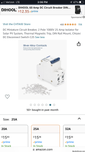
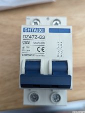
Do not like how they label that single pole breaker. A person not knowing better might think you hook up positive to bottom and negative to the top. You want the same polarity coming out of the breaker as going in. If that is the negative wire from panels it continues to be the negative wire to the SCC. Typically breakers are directional with the throw switch in On position towards line. In Off the throw switch is towards load. Since the solar panels are the supply that makes them line and your SCC is load.About to wire up a similar CHTAIXI breaker. So you’re saying that panels should be wired to the - connection port on top and the output (to SCC in my case) wired to the + port on bottom?
View attachment 153318
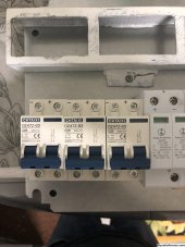
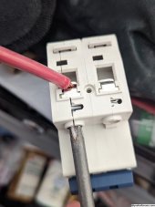
Personally I would use a 2 pole DC breaker to isolate panels and SCC. The one pictured looks more appropriate for a load breaker in a automotive/marine application where there is a common ground (neg or pos) so you just switch off the one input.


.jpg")