


You are using an out of date browser. It may not display this or other websites correctly.
You should upgrade or use an alternative browser.
You should upgrade or use an alternative browser.
I really want to use the Victron Battery Protect 220A
- Thread starter smitty201
- Start date
SCClockDr
Solar Enthusiast
Links would help the OP, I know it would me.Yes use a 500 amp 12/24 volt kilovac contactor and an under charge pcb. Total cost $50.
atatistcheff
Solar Enthusiast
- Joined
- Sep 20, 2019
- Messages
- 176
Do you mean it NEVER allows reverse current or only when the protection kicks in? My BP-65 allows me to charge the battery from the load side as long as the battery isn't below the protection voltage.
Justin Laureltec
Bay Marine Supply Tech Support Manager
Sorry to say it, but you've fried your BP... don't trust it anymore. As soon as reverse current is applied to a BatteryProtect, the FETs become wholly untrustworthy (welded open or shut) and the device will likely no longer disconnect your loads in an under-voltage condition.Do you mean it NEVER allows reverse current or only when the protection kicks in? My BP-65 allows me to charge the battery from the load side as long as the battery isn't below the protection voltage.
Victron has recently updated their online user manuals to reflect this: https://www.victronenergy.com/uploa...A-100-A--220-A-EN-NL-FR-DE-SE-SV-PT-TR-IT.pdf
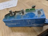
To be clear, the BatteryProtect doesn't stop reverse current... reverse current is just forbidden because it instantly damages the device and will very quickly start overheating and pose a potentially severe fire risk. See the photo I've attached of the result of ~20A of current being passed from the Out to the In of a BP100.
I strongly advise that you immediately remove that device from your system and either connect a replacement BP in an approved location or replace it with a suitable bidirectional voltage-sensitive relay that is capable of doing what you want in the position that you want it. There is a very good reason why reverse current through the BatteryProtect is strictly forbidden by Victron, and in the interest of your own safety as well as the safety of all the surrounding components, it's very important that you follow their instructions. In this case, unfortunately, your particular BP is already toast... so again, please remove that component from your system immediately.
Attachments
Last edited:
atatistcheff
Solar Enthusiast
- Joined
- Sep 20, 2019
- Messages
- 176
Holy crap that would have been nice to know. The instructions I received with the BP-65 say nothing about being sensitive to reverse current. I am extremely disappointed that Victron would sell a device that is so delicate and not put anything in the instructions (the ones included with the product) to indicate this. I see the updated pdf now has a note under #3 that warns about this but my instructions have no such note. I must say my confidence in Victron is severely shaken.
Maybe its my fault and I should just know how a battery protect works, but you would think that something this important would have been in the instructions.
Maybe its my fault and I should just know how a battery protect works, but you would think that something this important would have been in the instructions.
Justin Laureltec
Bay Marine Supply Tech Support Manager
Well the problem with Victron is that they're truly professional-grade and their components were designed, from the ground up, to be sold to professional installers who already know Victron systems inside and out... which was the case for the first 40 years of their life until, what, 5 or 6 years ago when they started hitting the US markets and being sold to end-users who didn't have decades of experience with Victron products. Victron as a company is slowly adjusting to the needs of their new demographic, but everything's taking time.Holy crap that would have been nice to know. The instructions I received with the BP-65 say nothing about being sensitive to reverse current. I am extremely disappointed that Victron would sell a device that is so delicate and not put anything in the instructions (the ones included with the product) to indicate this. I see the updated pdf now has a note under #3 that warns about this but my instructions have no such note. I must say my confidence in Victron is severely shaken.
Maybe its my fault and I should just know how a battery protect works, but you would think that something this important would have been in the instructions.
In this instance, they literally never considered the BPs being used in the way that people are using them: they were designed to be used in Victron systems, and since all Victron equipment already has user-adjustable low-voltage shutdowns built-in, Victron literally never thought to tell people NOT to connect them to inverters and inverter-chargers because -in their minds- that's clearly not where they go, and professionals would never put them there.
...except, as we all know, that's just not the case. People regularly mix components, and even professionals were frequently installing these things incorrectly... and it takes time for documentation to catch up with problems. The new manuals were only updated online a few weeks ago and now we can finally start moving ahead. In my case, we started including an insert that I printed with every BP we sell, saying THIS DEVICE IS UNIDIRECTIONAL, DO NOT CONNECT IN REVERSE but honestly a lot of people don't even know what that means, just like a lot of people don't read the manuals either. Of course, Victron manuals are a bit dense to get through sometimes anyway because -again- they're designed to be read and understood by professional installers, not necessarily end-users.
Bottom line, I wouldn't let it shake your faith in Victron, and I also wouldn't beat yourself up about it... just, when it comes to Victron components, take it as a lesson that really none of their components are as simple as they appear, and make sure to check for user manual updates and news on the website. The Victron Community is also a great resource for problems and questions: https://community.victronenergy.com/spaces/8/index.html Victron Energy staff -including the owner- are frequently on there answering questions and offering suggestions, as well as product experts such as myself and about a dozen others who actually do know these systems inside and out.
atatistcheff
Solar Enthusiast
- Joined
- Sep 20, 2019
- Messages
- 176
Thanks I appreciate your explanation. I have done plenty with electronics over the years but mostly microprocessors like Arduino, ESP-8266, etc. This high power stuff is newer to me. What you say makes sense but I really wonder how many of these are connected this way and may be unknowingly destroyed.
I just ran a test and it seems to be operating normally. Is there any way to tell if it has been damaged? I haven't run more than 8A @ 12V through it the wrong way. Might it be ok?
If it helps, here is how it's connected. Only the Victron 75/15 has been charging through it.

I just ran a test and it seems to be operating normally. Is there any way to tell if it has been damaged? I haven't run more than 8A @ 12V through it the wrong way. Might it be ok?
If it helps, here is how it's connected. Only the Victron 75/15 has been charging through it.
Justin Laureltec
Bay Marine Supply Tech Support Manager
Well the problem with these is there isn't a 100% positive way to tell if one of the FETs has been damaged... but the easiest test that I run (on a regular BP, the Smart BPs are far easier to troubleshoot), when I get these returned, is: pull out the remote switch plug (which should completely disconnect the device) and check for voltage at the "Out" terminal. Now, it's normal to show ~5v even when the remote jumper is pulled - this is just ghost voltage along the internal bus, but if you see more than that, it's probably bad. To further check it, (with the remote jumper still pulled), you can try connecting a very small load (like a 12v computer fan) to the "out" post and ground... if the fan budges even a little bit, that means one or more of the FETs has welded closed and is permitting some amount of current through the device when it's in a "disconnected" state... which means it's toast. There should be precisely 0 current running from "in" to "out" with the remote jumper removed.Thanks I appreciate your explanation. I have done plenty with electronics over the years but mostly microprocessors like Arduino, ESP-8266, etc. This high power stuff is newer to me. What you say makes sense but I really wonder how many of these are connected this way and may be unknowingly destroyed.
I just ran a test and it seems to be operating normally. Is there any way to tell if it has been damaged? I haven't run more than 8A @ 12V through it the wrong way. Might it be ok?
If it helps, here is how it's connected. Only the Victron 75/15 has been charging through it.
If you don't see any evidence of >5v voltage at the "out" post or any current leaking through, then your device may still be good... but tbh I still wouldn't trust it.
The good news is that most Victron distributors are aware of the issue and Victron is still very good about honoring warranty claims related to this issue. That won't last forever now that they've updated their manuals, of course, but they're well aware that they didn't spell out the weaknesses of these devices, so they're still honoring every warranty claim I've filed that's clearly a direct result of misconnection. I recommend that you get in touch with the distributor from who you purchased the device and start a warranty exchange process... but run those tests first so that you have some facts to give them.
Any Victron distributor is going to be very familiar with hearing "my BatteryProtect doesn't disconnect my load anymore" and shouldn't give you too much trouble over replacing it, though they should very clearly admonish you to never connect it that way again when you get the new one.
atatistcheff
Solar Enthusiast
- Joined
- Sep 20, 2019
- Messages
- 176
Thanks again and to the OP - sorry for hijacking your thread! Although I think this is an important issue to surface. I posted the schematic of my connections here in a thread a while back and nobody mentioned the incorrect connection of the Victron BP. Seems like we need to get the word out.
Justin Laureltec
Bay Marine Supply Tech Support Manager
Yeahhhh sorry, I've sort of become the BatteryProtect Police but I don't always see all the threads that come up in various forums mentioning BPs, so I miss some. This thread is (I think) where I first came into this forum, and anytime I see a BP mentioned anywhere I jump in to make sure it's being used appropriately... still miss some, tho.Thanks again and to the OP - sorry for hijacking your thread! Although I think this is an important issue to surface. I posted the schematic of my connections here in a thread a while back and nobody mentioned the incorrect connection of the Victron BP. Seems like we need to get the word out.
smitty201
New Member
- Joined
- Sep 23, 2019
- Messages
- 25
This has been a great discussion and I hope people learn from it. But the question remains, how can we make this BP work for us in a non Victron setup, using relays or whatever we need to do. I wanted the BP on a DIY LiFePO4 battery so I could set a more conservative low voltage cutoff than what the BMS is set to. Also I like the remote switch that I can use as a batt cutoff.
SCClockDr
Solar Enthusiast
I've looked @ their manual & I see their battery protect device as a one way deal battery >>> loads. Charging protects need a different approach.But I can't!
My RV system charges the batteries through the inverters and Battery Protect will not allow a charge voltage to feed back through it. Voltage only one way through the Battery Protect. Does anyone have a work around for this?
Justin Laureltec
Bay Marine Supply Tech Support Manager
Unfortunately, in a system with an inverter or inverter/charger, the BP simply cannot be used - it is one-way, period. I mean, you can still use it on a separate circuit feeding your regular 12v loads, but not on the main circuit feeding your inverter/etc which is what you're going for. Any proposed workaround, unfortunately, also works around the protection logic of the device, so you kinda just shoot yourself in the foot by trying things like that.This has been a great discussion and I hope people learn from it. But the question remains, how can we make this BP work for us in a non Victron setup, using relays or whatever we need to do. I wanted the BP on a DIY LiFePO4 battery so I could set a more conservative low voltage cutoff than what the BMS is set to. Also I like the remote switch that I can use as a batt cutoff.
There are a variety of VSRs, however, that may be more suited to your needs. The only one I can personally recommend, because I've personally tested it and found it to be reliable, is the Sterling ProLatch-R, which has a "battery protect" mode which is fully programmable (not over bluetooth, alas, it's a bloody pain to program but is bulletproof once you've got it set), is bistable, low self-consumption (because it's magnetically latching), capable of handling high amperages (up to 240A), waterproof, and is specifically designed to be able to handle the high inrush currents of inverters and inverter-chargers.
It's not cheap (the 240A is about $40 or so more than the Victron Smart BP220) and it's a horrible pain to program, as I mentioned (such a pain that for our customers' sake I had to write my own manual for the thing) but it's suitable for the application, reliable as hell, and won't melt when you run reverse current through it.
Justin Laureltec
Bay Marine Supply Tech Support Manager
Always happy to help! It's worth noting that I'm sure there are alternatives to the Sterling, and likely far cheaper ones, it's just I don't recommend products that I haven't personally had either installed in my own systems or had on my test bench for an extremely thorough round of stress testing, so I can't personally speak to the alternatives.Thanks Justin for sharing your knowledge!
Bluemalibu
New Member
it's a horrible pain to program, as I mentioned (such a pain that for our customers' sake I had to write my own manual for the thing)
Justin, how soon will you have the flag battery terminals available for sale? That looks perfect for paralleling my four BYD batteries with 4/0 AWG.
Secondly, will you be carrying the Blue Sea ML series link busbars?
Lastly, is your manual for the 240A ProLatch down-loadable? Thanks so much...
SCClockDr
Solar Enthusiast
Your load could be a hi current solenoid & run all your battery loads through that. You would then have a 2 way street.
BUT
If the battery goes too low
BUT
If the battery goes too low
Justin Laureltec
Bay Marine Supply Tech Support Manager
Hmmm the FTZ flag terminals? We have those on our site and on eBay. We're not looking into the Blue Sea ML series because we have a contract with BEP Marinco on their Pro Installer series of components, which are very similar in design and function.Justin, how soon will you have the flag battery terminals available for sale? That looks perfect for paralleling my four BYD batteries with 4/0 AWG.
Secondly, will you be carrying the Blue Sea ML series link busbars?
Lastly, is your manual for the 240A ProLatch down-loadable? Thanks so much...
For the manual I wrote, you'll need to download Sterling's manual first, since it has charts that you need and I cross-reference several points. We don't provide my manual as a general download because we include a printed copy when someone orders a ProLatch, but I've attached a pdf here for you.
Attachments
Bluemalibu
New Member
You are too good... thanks so much!
Similar threads
- Replies
- 1
- Views
- 133
- Replies
- 3
- Views
- 520
- Replies
- 1
- Views
- 155